Cutting tool

a cutting tool and tool body technology, applied in the field of cutting tools, can solve the problems of short service life and poor reliability, inability to withstand a further increase in cutting speed, and low machining efficiency of grinding, and achieve the effect of secure stable cutting performance and low cos

Inactive Publication Date: 2005-09-06
NGK SPARK PLUG CO LTD
View PDF12 Cites 17 Cited by
  • Summary
  • Abstract
  • Description
  • Claims
  • Application Information

AI Technical Summary

Benefits of technology

[0008]It is therefore an object of the present invention to provide a ceramic cutting tool which can be fabricated at low cost and which can secure stable cutting performance over a long period even when the tool is used under severe cutting conditions, for example, when the tool is used for cutting a hard material, under which large thermal and mechanical loads act on the tool.

Problems solved by technology

However, grinding involves a problem of low machining efficiency.
Recently, cBN tools have often been used, because a ceramic tool formed of alumina-titanium carbide composite ceramic has a short service life and poor reliability, and cannot withstand a further increase in cutting speed.
Although cBN tools provide excellent cutting performance, they are very expensive, because cBN tools are fabricated by utilizing a super-high pressure technique as in the case of artificial diamond, thereby hindering the popularization of cBN tools.
However, in the techniques disclosed in the above patent publications, since inadequate consideration is given to residual stress produced in the coating film at the time of its formation, great improvement in performance cannot be expected.
Moreover, when the coating layer is composed of a plurality of sub-layers of different materials having different coefficients of thermal expansion, the differences in coefficient of thermal expansion among the sub-layers cause generation of residual stress.
Although ceramic tools have excellent wear resistance as compared with tools formed of high-speed tool steel or cemented carbide alloy, they have insufficient fracture resistance, and particularly insufficient resistance to flaking fracture (flaking of a cutting edge to a shell-like shape) which occurs during machining of the above-mentioned hard materials to shorten the service life thereof.
Therefore, even when the above-mentioned coating layer is provided, satisfactory performance in terms of fracture resistance cannot be expected if a large residual stress is produced in the coating layer.
Moreover, the problem of residual stress arises not only during formation of a coating layer but also during actual machining.
Since a tool is heated to high temperature due to contact friction between the tool and a workpiece during actual machining, when the tool is used repeatedly, thermal shock repeatedly acts on the tool due to the repeated cycles of heating and cooling.
As a result, tensile residual stress is produced in the coating layer during cooling which is performed after forming the layer by CVD, which tensile residual stress also lowers the fracture resistance of the tool.
However, the above-described problem has been an obstacle in such development.

Method used


Image

  • Cutting tool
  • Cutting tool
  • Cutting tool

Examples


Embodiment Construction

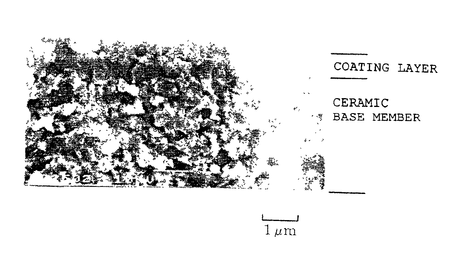
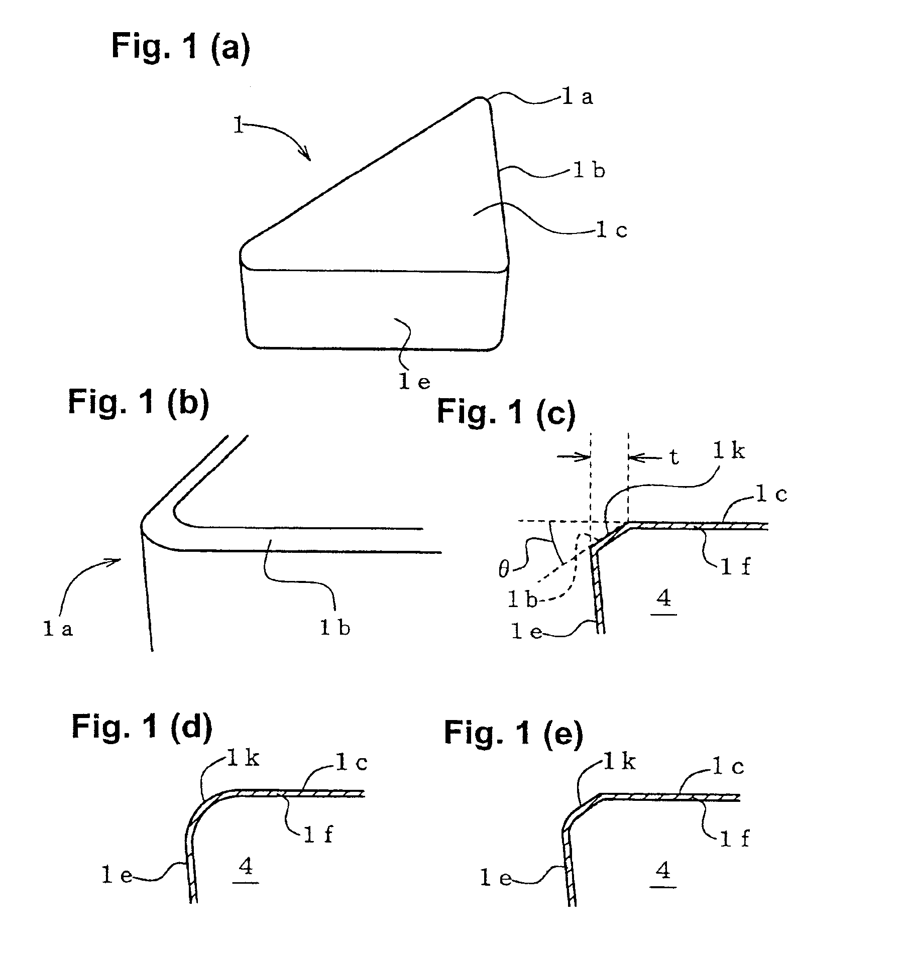
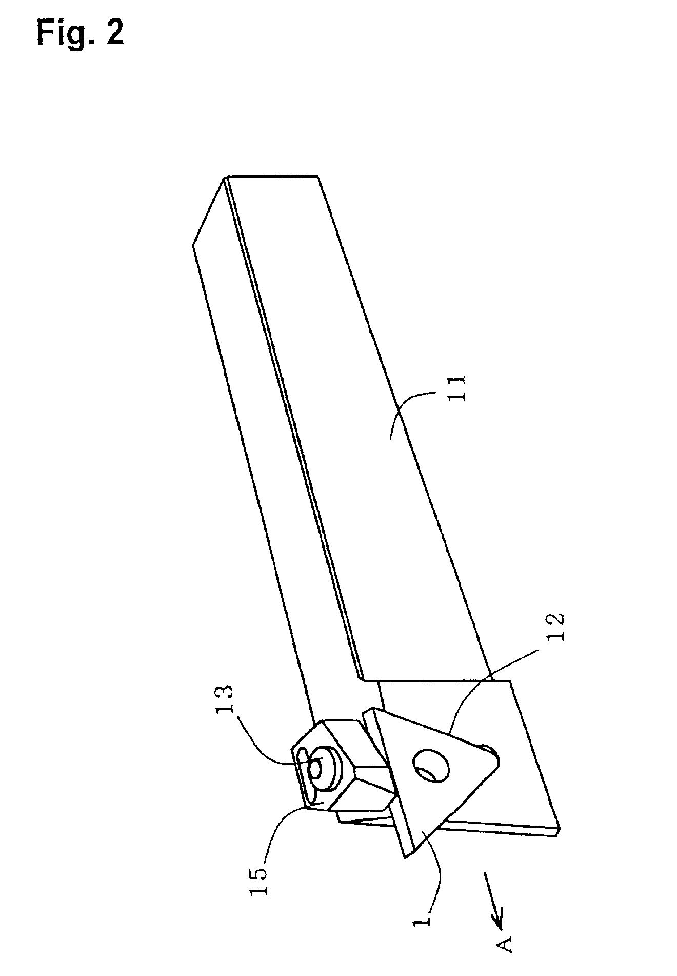
[0036]FIG. 1 depicts one embodiment of the ceramic cutting tool of the present invention and shows a throw-away tip (hereinafter simply referred to as a “tip”) 1, serving as a tool main body of the cutting tool. As shown FIG. 1(a), the tip 1 has a structure such that the entire outer surface of a ceramic base member 4 formed in the form of a flat, substantially rectangular prism is covered with a coating layer 1f shown in FIG. 1(c). A main face 1c of the tip 1 forms a cutting face (hereinafter also referred to as a “cutting face 1c”), and each side face 1e forms a flank (hereinafter also referred to as a “flank 1e” as well). Each corner 1a of the tip 1 is rounded as shown in FIG. 1(b), and a chamfer 1k is formed for a corresponding cutting edge 1b as shown in FIG. 1(c). The chamfer 1k provides a flat surface as viewed along its cross section and is adjusted such that the angle θ formed between the chamfer 1k and the main face 1c serving as a cutting face falls within a range of 20 t...


PUM

PropertyMeasurementUnit
thicknessaaaaaaaaaa
crystal-grain sizeaaaaaaaaaa
temperatureaaaaaaaaaa

Abstract

A ceramic cutting tool including a ceramic base member 4 of a tool main body 1 which is formed of a composite ceramic which contains a hard phase dispersed within an alumina matrix phase. The hard phase contains, as a predominant component, one or more elements selected from hard-phase-forming metal elements M in the form of at least one of a carbide, nitride, or boride, or in the form of a solid solution of at least two selected from the carbide, nitride and boride. The hard-phase-forming metal elements M include Ti, Zr, Hf, V, Nb, Ta, Cr, Mo, W and Si. The surface of the ceramic base member 4 is covered with a coating layer 1f, which contains titanium carbonitride or titanium nitride as a predominant component. The coating layer 1f has an average crystal-grain size of 0.1 to 0.5 μm as observed on the surface, and an average thickness of 0.5 to 2 μm. The coating layer 4f is formed by a CVD at a low to medium temperature range of 750 to 900° C. The ceramic cutting tool can be fabricated at low cost and can secure stable cutting performance over a long period even when the tool is used under severe cutting conditions under which large thermal and mechanical loads act on the tool.

Description

BACKGROUND OF THE INVENTION[0001]1. Field of the Invention[0002]The present invention relates to a cutting tool having a tool main body formed of ceramic which can be used as a throw-away tip, an end mill, a drill, or the like, and more particularly, to a cutting tool in which a surface coating is provided on the tool main body formed of ceramic to improve wear resistance.[0003]2. Description of the Related Art[0004]Conventionally, hard materials, such as carburized and quenched steel, die steel and tool steel, have been ground by use of a grinding stone. However, grinding involves a problem of low machining efficiency. Therefore, in order to perform machining at higher speeds, attempts have been made to replace grinding with cutting using a cBN (cubic Boron Nitride) tool or a ceramic tool formed of an alumina-titanium carbide composite ceramic. Recently, cBN tools have often been used, because a ceramic tool formed of alumina-titanium carbide composite ceramic has a short service l...

Claims


Application Information

Patent Timeline
Patent Type & Authority Patents(United States)
IPC IPC(8): B23B27/14C23C16/30
CPCB23B27/145B23B2200/242B23B2200/245Y10T428/265Y10T407/27Y10T428/252Y10T407/24C23C16/30
Inventor KATO, HIDEKIHATANO, YUKIYUKIMACHI, HIDEAKI
Owner NGK SPARK PLUG CO LTD
Why Eureka
Try Eureka