
Flushing system and process

a technology of flushing system and process, applied in the direction of steam power plant, marine propulsion, vessel construction, etc., can solve the problems of component failure, marine engine and/or outdrive components, failure to properly complete the task, etc., and achieve the effect of novel in its simplicity of design and use, simple, inexpensive and reliabl

Inactive Publication Date: 2005-09-20
AKHAVEIN GLENN
View PDF9 Cites 8 Cited by
  • Summary
  • Abstract
  • Description
  • Claims
  • Application Information

AI Technical Summary

Benefits of technology

"The invention is a simple and reliable method for flushing marine engines, inboards, or outboards while they are running and the vessel is either in or out of the water. The device can be easily installed and is designed to provide a foolproof flushing process. It allows for the monitoring of the engine cooling water and can also be used as an emergency device in case of a loss of life or vessel. The device is designed to be easily installed and can be done so with minimal tools. It is also designed to be simple and close to the markets it serves."

Problems solved by technology

The combination of complicated operational procedures, fluid flow design and flow design components, and the physical locations of such prior art devices often presents the risk that an improper operational procedure or an unknown malfunction of a fluid flow component will expose the vessel to taking on seawater, not functioning correctly under normal operation which can result in ruining a marine engine and / or outdrive components, or at the very least, not properly completing the task for which they are designed, that is, thoroughly flushing a marine engine.
While these devices avoid the need for manual intervention, the constant exposure to corrosive environments, abrasive contaminants such as sand and mud, and larger floating debris, can lead to component failure, valve seat failure, as well as failure due to large debris being trapped within the device.
This all leads to an inherently unreliable fluid control system over the life of the vessel.
The other significant limitation to both of these devices is that they cannot be used with an inboard / outboard marine engine that has the coolant pump in the outdrive.
If fluid from the outdrive is not allowed to continue to flow, the pressure on the outlet of the outdrive pump will increase and the pump will, in a matter of just a few minutes, fail.
However, both of these devices rely upon complicated assemblies and components.
As with the previously mentioned devices, the constant exposure to corrosive environments, abrasive contaminants such as sand and mud, and larger floating debris, can lead to component failure, valve seat failure, as well as failure due to large debris being trapped within the devices.
This all leads to an inherently unreliable fluid control system over the life of the vessel.
Patti's device consists of a long tubular assembly having a shutoff valve between a seawater inlet and outlet, a second shutoff valve between a freshwater inlet and outlet, and a complicated process for changing from normal operation to flushing and then back again to normal operation.
However, the device is dramatically more complicated, which makes it more susceptible to the failures mentioned above, and it is a much more expensive design due to the number of sliding seals and the inherent difficulty maintaining this style of seal in the presence of so many abrasive contaminants.
This leads to another problem for both Patti's and Bates' devices; the potential to have port-to-port leakage during the flushing process that cannot be easily determined, if at all.
Over time, if there is wear on the seals, valve seats, or in Bates' case, the body material between the two seals, there can be port-to-port leakage.
This has the potential of introducing contaminants and saltwater into the engine during the flushing cycle.
Since this is not easily determined, if at all, the signs of this happening will not be apparent until there is substantial damage to the engine, exhaust manifold, or risers, all of which are very expensive to replace.
As previously mentioned, both Patti's and Bates' devices can be used with an inboard or an inboard / outboard marine engine; however, neither of these devices can be used to flush a marine engine with an outdrive pump while the engine is running and the boat is out of the water.
If the engine is off, the cold flushing fluid will immediately cause the thermostat to close, which will in turn close off much of the engine to the flushing fluid thereby dramatically shortening the life of the marine engine.
Brogdon's flushing system does not fit into the existing normal forward flow path of fluid used to flush the engine.
A portion of Brogdon's system is attached to the drain or outlet of the engine; however, the normal fluid traveling from the body of water that the vessel is in, through the seawater pump, and onto the engine never passes through the flushing system.
These two differences dramatically affect the overall use of the system.
More importantly, the Brogdon flushing system cannot be used on an inboard / outboard engine that has the seawater pump in the outdrive.
There is no means by which to keep the outdrive impeller pump from overheating and melting.
The next problem, (shortcoming), is introducing flushing fluid directly into multiple parts of the engine to attempt back flush the system.
If water is introduced to various parts of a marine engine without having separate flow and pressure restrictors placed on the individual areas that being flushed, the flushing fluid will flow through the paths of least resistance and never reach many of the parts of the engine that get the hottest and / or have the most difficult deposits to remove.
Creating this high pressure within marine engines can have dire consequences.
The portions of the engine that have elastomeric seals are prone to failing when subjected to high pressures.
They are even more prone to failure when subjected to high pressures in the opposite direction that they were designed to seal against.

Method used


Image

  • Flushing system and process
  • Flushing system and process
  • Flushing system and process

Examples


Embodiment Construction

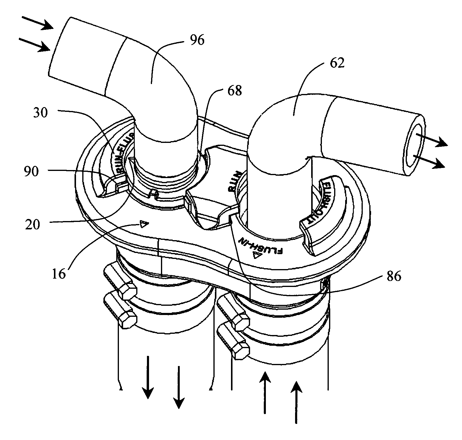
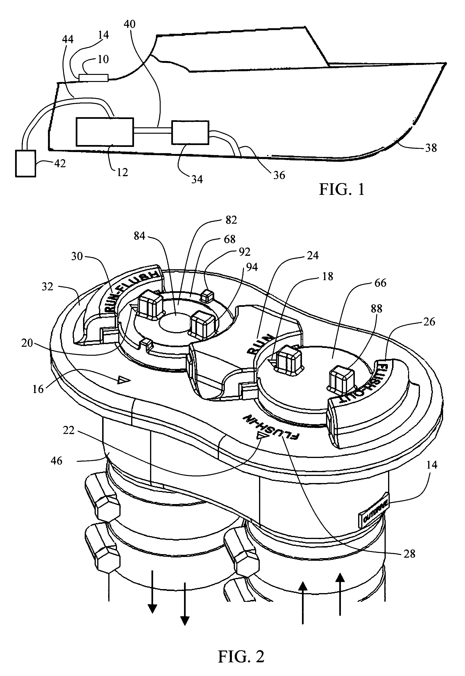
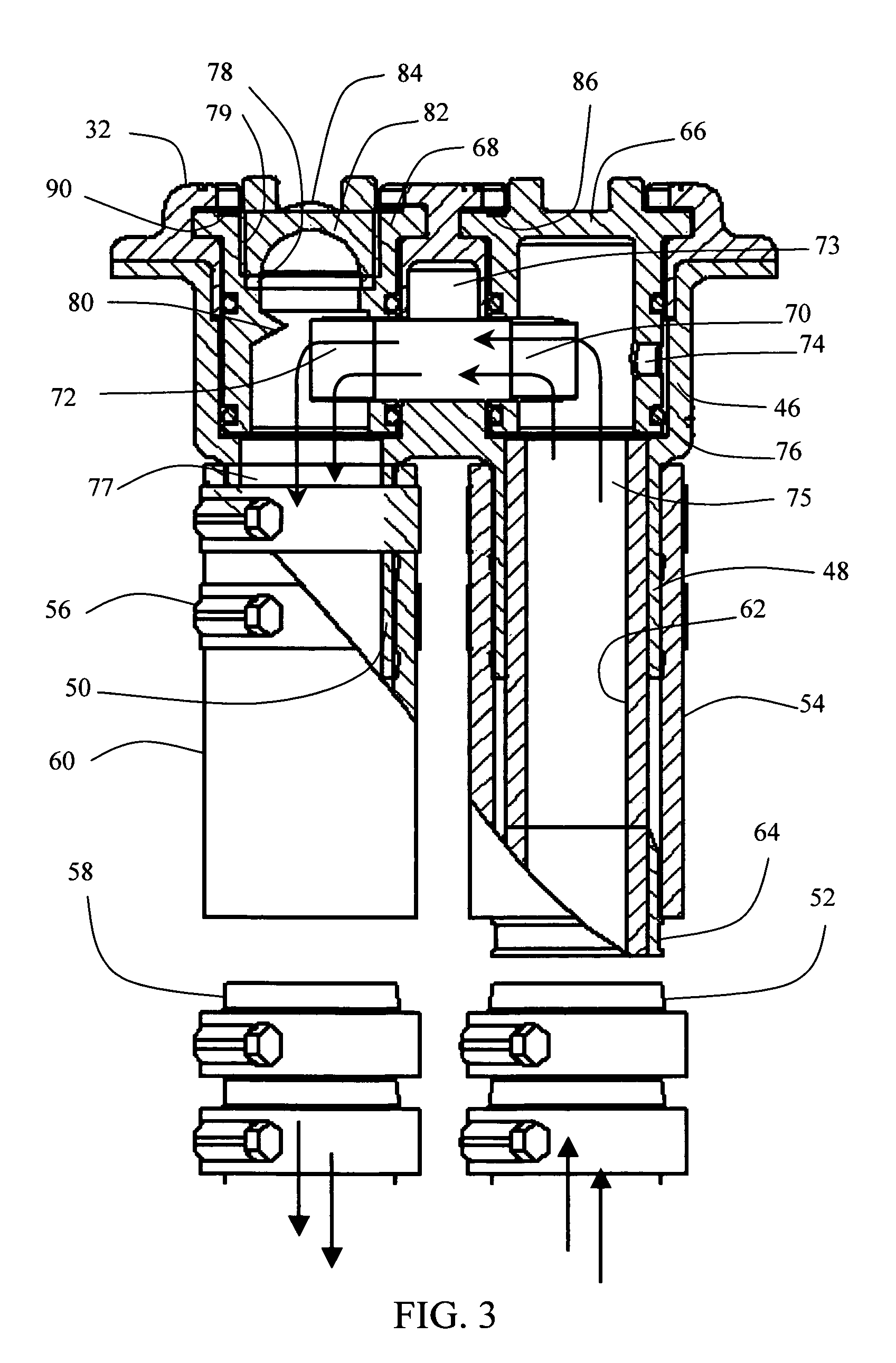
[0047]FIG. 1 shows one possible mounting location for the flushing system 10 relative to the vessel's engine 12. The flushing system 10 is generally installed in the gunwale or the top of the transom. If the flushing system 10 is installed along the side of the vessel, in the gunwale, the propeller indicator 14 points towards the back of the vessel. If the flushing system 10 is installed in the top of the transom, the propeller indicator 14 points towards the center of the vessel. This aids in making the flushing system 10 more intuitive. There are pointers FIG. 2: 16, 18, 20 and 22, and verbal descriptions, 24, 26, 28 and 30, built into the cover 32 that also aid in making the flushing system 10 easy to use. The specific uses for each will be discussed in detail.

[0048]The insertion point for the flushing system 10 varies depending upon the type of vessel. For a vessel with a seawater pump 34 in the engine compartment, the flushing system 10 can be spliced into either the conduit 36...


PUM


Abstract

A flushing system for an inboard and an inboard / outboard marine engine is inserted into the flow path normally used for conducting ambient water to the engine for cooling purposes. A first attachment means allows ambient fluid to flow into the system and a second attachment means allows for ambient fluid to flow out of the system. A first extension means connects the upstream ambient fluid to the flushing system inlet and a second extension means connects the flushing system outlet to the downstream ambient fluid allowing the flushing system to be located some distance from the insertion point.

Description

BACKGROUND OF THE INVENTION[0001]1. Field of the Invention[0002]This invention relates to a novel, yet simple system and process for flushing inboard / outboard marine engines and inboard marine engines with a desired fluid. This system and process allows for any person to quickly and easily flush an engine whether the boat is in the water or out of the water with the engine running.[0003]The need for such systems is commonly seen with marine engines. When a marine engine is operated, in fresh water or salt water, impurities in the water can cause cooling problems and corrosion of components if not properly flushed. Debris of various types can be picked up in lakes and rivers, and even the cleanest ocean water is going to have salt in it. Therefore, it is imperative that marine engines get flushed after every use.[0004]The difficulty is that flushing marine engines, especially some inboard / outboard engines, can be very cumbersome since the intake for cooling fluids is in the vicinity ...

Claims


Application Information

Patent Timeline
Patent Type & Authority Patents(United States)
IPC IPC(8): B63H21/00B63H21/10B63H20/30F01P3/20
CPCB63H20/30F01P3/205
Inventor AKHAVEIN, GLENN
Owner AKHAVEIN GLENN
Learn More