
Volumetric physiological measuring system and method

a physiological measurement and volumetric technology, applied in the field of volumetric physiological measurement system and method, can solve the problems of inability to obtain reliable data, crude and inaccurate measurements, and inability to use airway-based techniques, so as to reduce the demands for circuit cooling and power supply capacity, reduce the noise of the system, and reduce the total power consumption of the amplifier unit.

Inactive Publication Date: 2005-09-20
VOLUSENSE AS
View PDF16 Cites 19 Cited by
  • Summary
  • Abstract
  • Description
  • Claims
  • Application Information

AI Technical Summary

Benefits of technology

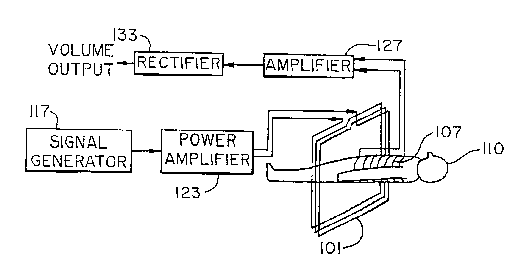
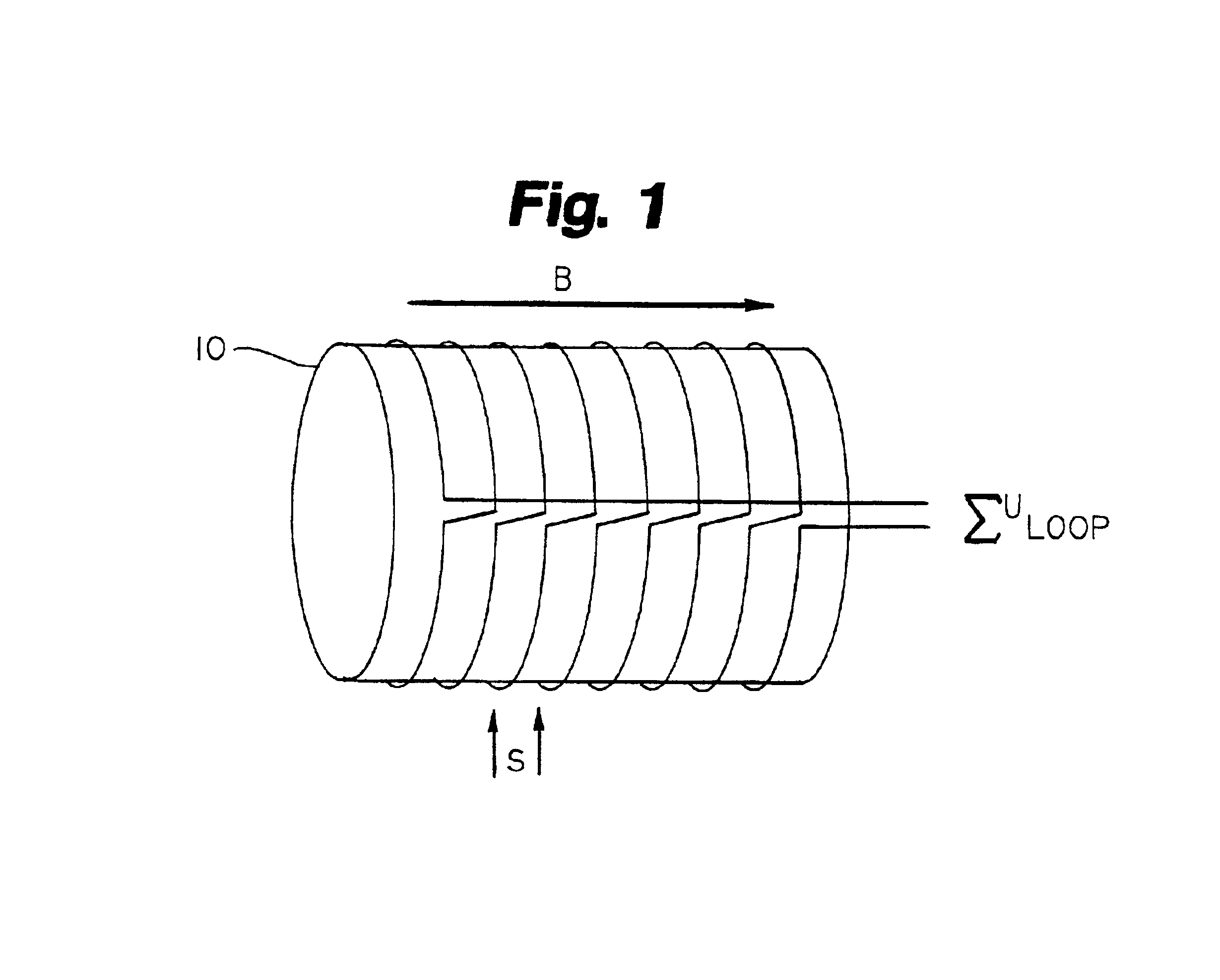
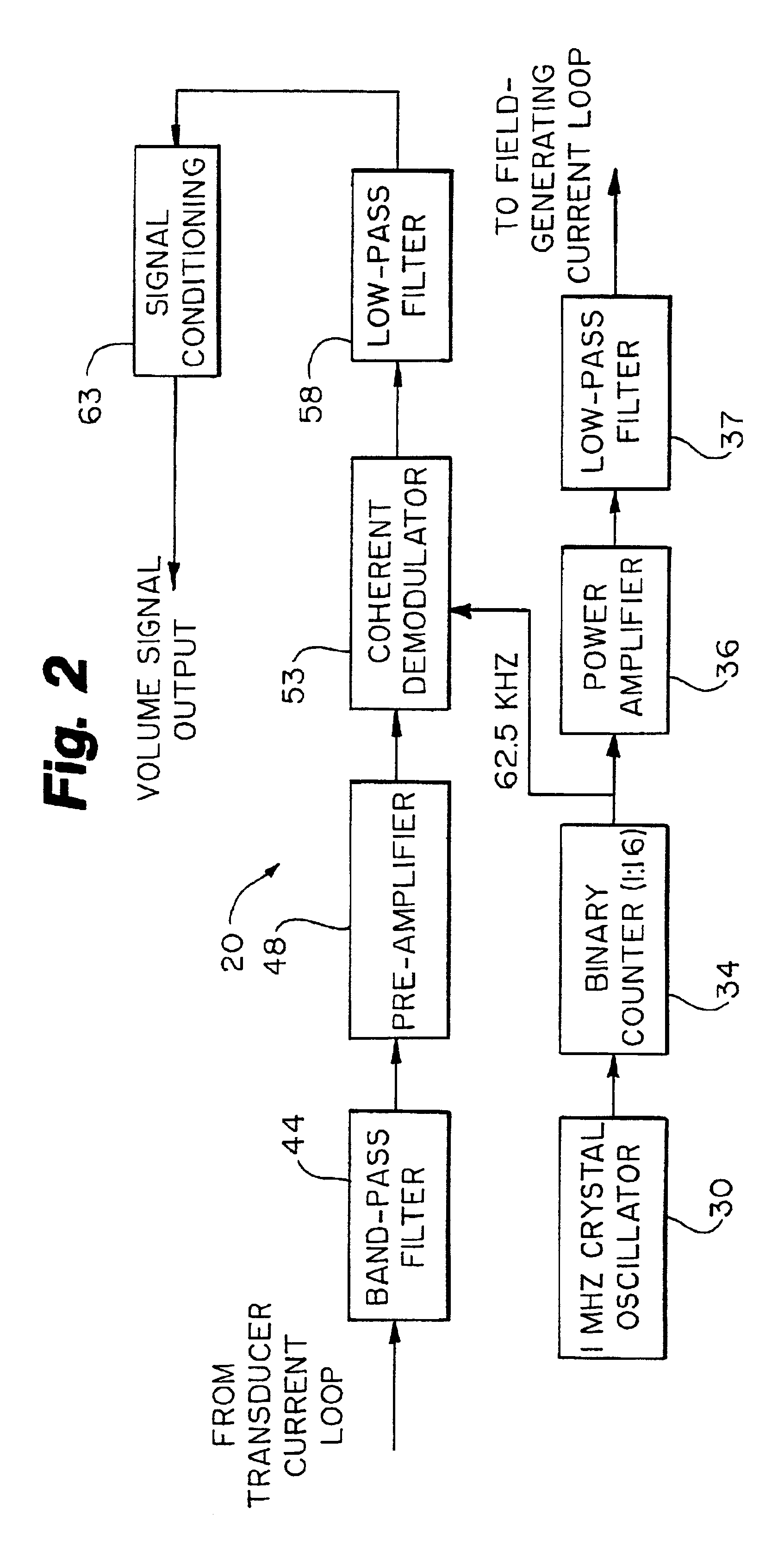
[0028]Summation of the induced voltages is accomplished by electrical serial connection of the loops, effectively reducing the complexity of the system, since only one voltage needs to be measured. This is an important advantage of the invention disclosed herein resulting in reduced system complexity. The choice of the loop spacing s (also referred interchangeably herein as distance d) is a compromise between accuracy and convenience in the design of the volume transducer. A low value of s means that a higher number of loops will be needed to encompass the measurement region, which typically is from the level of the axilla and down to the crest of the hips, when measuring a torso. If the number of loops becomes high, the self-inductance of the serially connected loops starts to increase dramatically, with implications for the design of the electronic circuits. A preferable embodiment is to use values of s in the range of four to eight cm, which are the smallest values to be used for infants. This typically results in eight (8) to ten (10) loops. Other configurations, however, are possible. The magnetic field need only be homogeneous within the volume occupied by the relevant parts of the patient's body or other object being measured. Practical experience indicates that a field of sufficient intensity and homogeneity can be generated just by arranging a conductor wire as a vertical rectangular loop, following the floor, walls and ceiling of the room, and feeding an alternating current through the loop. Preferable values are 10 kHz to 200 kHz with currents below 1 A, although other configurations are possible. For example, more than one electrical conductor loop may be used.

Problems solved by technology

Unfortunately these measurements are often crude and inaccurate, or at best rely upon outmoded technical modalities or upon unreliable.
For long-term monitoring purposes, the airway-based techniques are inappropriate since they interfere with normal breathing and are unpleasant for the patient.
Although airway-based techniques are currently used in patients dependent on respiratory-assist devices there may be less intrusive and more reliable means of obtaining such data.
Unfortunately, this is not the case for the cross-sectional area variations of the human chest or abdomen that are caused by respiration.
Common to all area-based methods is a considerable uncertainty in the calculations of volume variations from the estimated area variations.
The calibration procedure depends highly upon patient cooperation to obtain coefficients for both chest and abdominal measurement sites, and is virtually inapplicable to small children, patients with dyspnea (shortness of breath), and unconscious patients.

Method used


Image

  • Volumetric physiological measuring system and method
  • Volumetric physiological measuring system and method
  • Volumetric physiological measuring system and method

Examples


example 1

[0056]A circular electrical conductor loop with a radius of 1.5 meters was placed on the floor. An alternating current of 0.1 A with a frequency of 100 kHz was fed through the conductor from a signal generator. A small, 10×10 cm (100 cm2) square conductor loop was connected to the input of a broadband signal amplifier with a gain of 40 dB, and the output from this amplifier was passed through a narrow 100 kHz band-pass filter with no gain. The output signal from the filter was presented on an oscilloscope screen, where voltages could be read by cursors. When the small loop was positioned flat on the floor in the center of the larger current loop, a voltage of 5 mV p / p was measured. This voltage remained essentially constant when the small loop was elevated 50 cm above the floor, and it also remained constant when the small loop was moved up to 50 cm in any horizontal direction away from the center of the large current loop. Another square loop, measuring 14.1×14.1 cm, with an area o...

example 2

[0057]The same conductor loops as described in Example 1 were used, but the 0.1 A current from the signal generator was fed to the 100 cm loop, and the large loop on the floor was connected to the input of the 40 dB broadband amplifier. The small loop was positioned as explained in Example 1. The same general relations between induced voltage and loop position and area was observed as in Example 1, however the voltages were reduced to 250 μV when using the 100 cm2 loop, and 500 pV when using the 200 cm2 loop.

example 3

[0058]Referring to FIG. 11, three identical cylindrical ferrite rods 175 with a diameter of 8 mm, length of 150 mm and permeability of 100 were arranged along a straight horizontal line with a common axis. The end-to-end horizontal spacing between each rod was 50 cm. The two outer coils were equipped with 163 turns of lacquer-insulated 0.1 mm copper wire evenly distributed along a central 8 cm segment of the rod, while the center rod had 100 turns arranged in the same manner. The coils were electrically connected in series, and care was taken to assure identical current directions in all coils. The serially connected coils were then tuned to parallel resonance at 100 kHz with a common capacitor 177 of about 10 nF. An oscilloscope directly monitored the signal from the resonant circuit. A 10 cm×10 cm current loop carrying a 100 kHz alternating current of 0.1 A was positioned adjacent to the coil assembly, keeping the orientation of the loop perpendicular to the ferrite rods common ax...


PUM


Abstract

A system and method for measuring volumes and areas using electromagnetic induction techniques. A current is generated and fed into one of two coil assemblies to induce voltage into another coil assembly to provide accurate values for volume or area.

Description

CROSS-REFERENCE TO RELATED APPLICATION[0001]This application is a division of U.S. patent application Ser. No. 09 / 428,358 filed Oct. 28, 1999, now U.S. Pat. No. 6,374,667 which is incorporated herein by reference, and claims benefit U.S. Provisional Application No. 60 / 106,282 filed Oct. 30, 1998.FIELD OF THE INVENTION[0002]The invention relates to a system and method for accurate measurements of volume and area of objects, utilizing electromagnetic induction techniques.BACKGROUND OF THE INVENTION[0003]Numerous opportunities exist in which accurate measurements of volume and area are essential, particularly of objects or portions of objects having variable volumes or areas. For example, in the field of medicine, the recording of breathing volumes in patients is often quite critical. Unfortunately these measurements are often crude and inaccurate, or at best rely upon outmoded technical modalities or upon unreliable. The recording of breathing volumes in patients is currently either p...

Claims


Application Information

Patent Timeline
IPC IPC(8): A61B5/06A61B5/113A61B5/11G01F17/00A61B5/05A61B5/103G01B7/00G01B7/28G01B7/32
CPCA61B5/06A61B5/1135A61B5/6802A61B5/7203A61B5/7278A61B5/05A61B5/091A61B5/1073
Inventor ERIKSEN, MORTENERIKSEN, ERIK
Owner VOLUSENSE AS
Learn More