Line reflection reduction with energy-recovery driver

a technology of energy recovery and driver, which is applied in the field of line drivers, can solve the problems of increasing the voltage on the transmission line to exceed the allowable or safe level, reducing the noise margin of line reflection in high-speed digital circuits, and reducing the noise margin of line reflection. , to achieve the effect of reducing ringing, increasing power dissipation, and reducing ringing

Inactive Publication Date: 2005-09-20
UNIV OF SOUTHERN CALIFORNIA
View PDF16 Cites 10 Cited by
  • Summary
  • Abstract
  • Description
  • Claims
  • Application Information

AI Technical Summary

Benefits of technology

[0016]Another object of the invention is to reduce ringing in transmission-line driving systems.
[0017]A still further object of the invention is to reduce ringing in transmission-line driving systems without increasing power dissipation.
[0018]A still further object of the invention is to reduce the maximum voltage-level specificat

Problems solved by technology

Line reflection decreases the noise margin in high-speed digital circuits, especially line reflections induced by signal buffers driving off-chip loads.
Ringing often creates problems.
It often causes the voltage on the transmission line to exceed allowable or safe levels.
This approach, however, causes additional power to be dissipated in

Method used


Image

  • Line reflection reduction with energy-recovery driver
  • Line reflection reduction with energy-recovery driver
  • Line reflection reduction with energy-recovery driver

Examples


Embodiment Construction

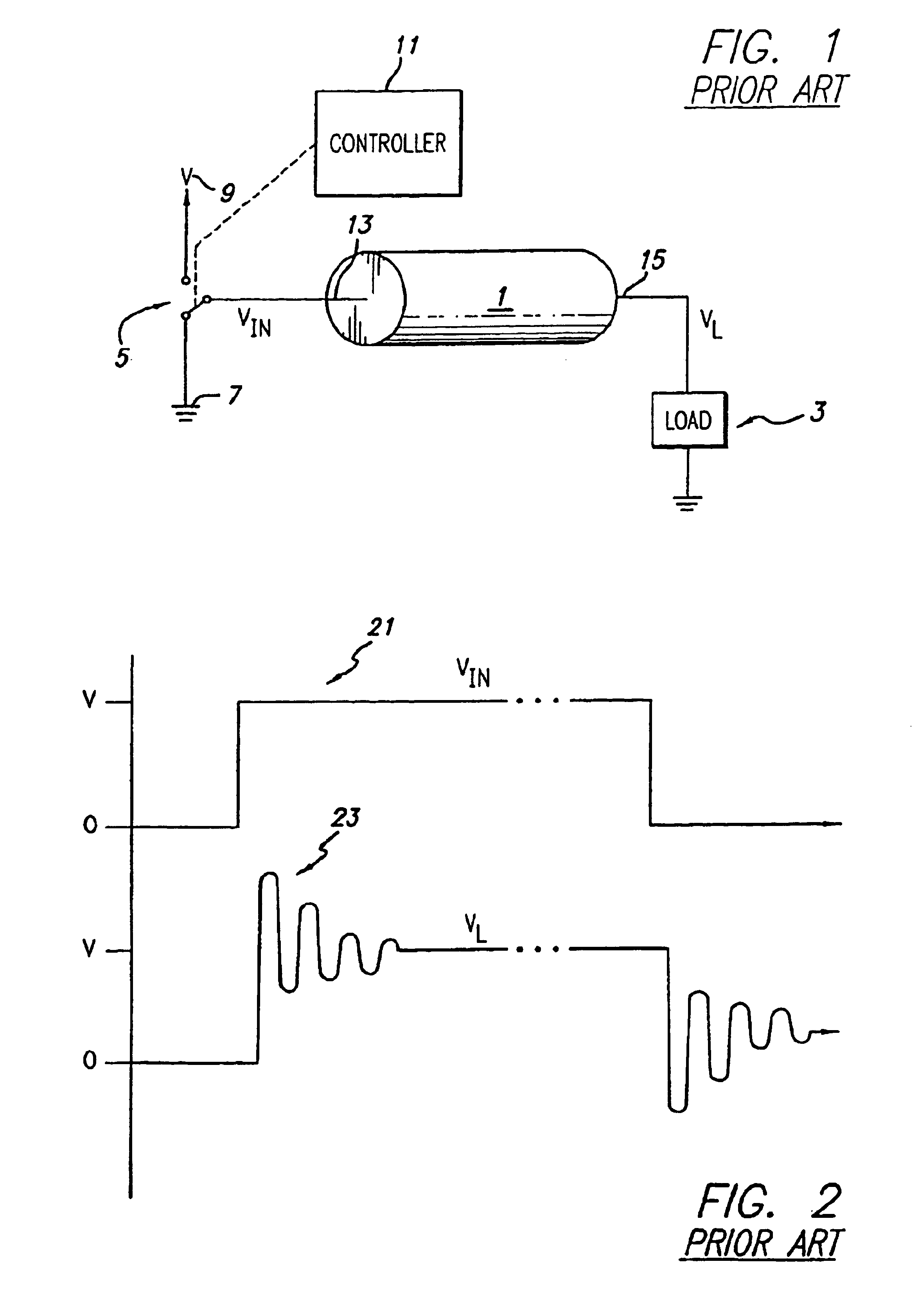
[0047]FIG. 1 illustrates a prior art line driver system.

[0048]As shown in FIG. 1, a transmission line 1 delivers a voltage VL to a load 3.

[0049]The transmission line 1 is driven by a driver. The driver includes a signal generation system, including a switch 5, a first drive signal 7 (which is shown in this example as being ground) and a second drive signal 9 (which is shown as being a source of voltage V). The signal generation system is connected to a controller 11 which electronically controls the switch 5, thus causing VIN at an input 13 of the transmission line 1 to switch between the first drive signal 7 (ground) and the second drive signal 9 (V). In a typical configuration, the switch 5 is an electronic switch, such as a FET, MOSFET, SCR, triac or BJT.

[0050]The goal of the prior art line driver system shown in FIG. 1, of course, is to cause VL at an output 15 of the transmission line that is across the load 3 to switch between the levels of the first drive signal (ground) and ...


PUM


Abstract

A system and method for reducing reflections in a transmission line and for recovering energy from the load in the transmission during the process. At least three drive signal levels are utilized. The transition from the second level to the third level during a rising transition and the transition from the second level to the first level during a falling transition is timed to coincide with the arrival of the reflected signal from the immediately-preceding transition. A capacitor is advantageously used as the source for the intermediate drive signal levels and advantageously facilitates energy recovery and conservation.

Description

CROSS-REFERENCE TO RELATED APPLICATION[0001]This application is a continuation of application Ser. No. 10 / 270,851, filed Oct. 14, 2002 is now a U.S. Pat. No. 6,696,853, entitled “Line Reflection Reduction with Energy-Recovery Driver,” which is a continuation of application Ser. No. 09 / 532,798, filed Mar. 21, 2000 is now a U.S. Pat. No. 6,486,697, entitled “Line Reflection Reduction with Energy-Recovery Driver,” the contents of which are incorporated herein by reference.[0002]application Ser. No. 09 / 532,798 claimed the benefit of U.S. Provisional Application No. 60 / 125,580, filed Mar. 22, 1999, entitled “Line Reflection Cancellation with Energy-Recovery Driver,” the contents of which are incorporated herein by reference.GOVERNMENT LICENSE RIGHTS[0003]The invention was made with government support under DAAL01-95-K-3528 sponsored by DARPA and MDA904-93-C-L042 sponsored by DOD. The government has certain rights in the invention.BACKGROUND OF THE INVENTION[0004]1. Field of the Invention...

Claims


Application Information

Patent Timeline
IPC IPC(8): H04L25/02
CPCH03K3/00H03K19/0005H03K19/0019H04L25/0278H04L25/028H04L25/0286H04L25/0298H03K17/00
Inventor SVENSSON, LARS G.ATHAS, WILLIAM C.
Owner UNIV OF SOUTHERN CALIFORNIA
Why Eureka
Try Eureka