
Exhaust gas cleaning system of internal combustion engine

Active Publication Date: 2005-10-04
DENSO CORP
View PDF7 Cites 53 Cited by
  • Summary
  • Abstract
  • Description
  • Claims
  • Application Information

AI Technical Summary

Benefits of technology

[0012]It is therefore an object of the present invention to provide an exhaust gas cleaning system for an internal combustion engine capable of preventing excessive accumulation of particulate matters in a DPF beyond a permissible quantity. Thus, degradation of an output of the internal combustion engine can be prevented, and degradation or damage of the DPF and a catalyst, which may be caused when the large amount of the particulate matters is combusted rapidly, can be prevented. Thus, a safe and high-performance exhaust gas cleaning system can be provided.
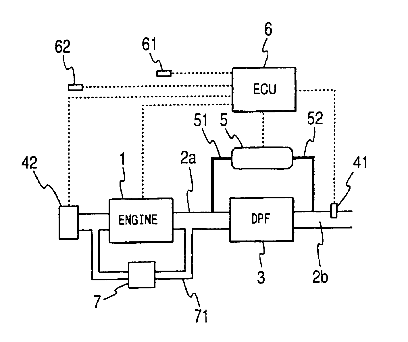
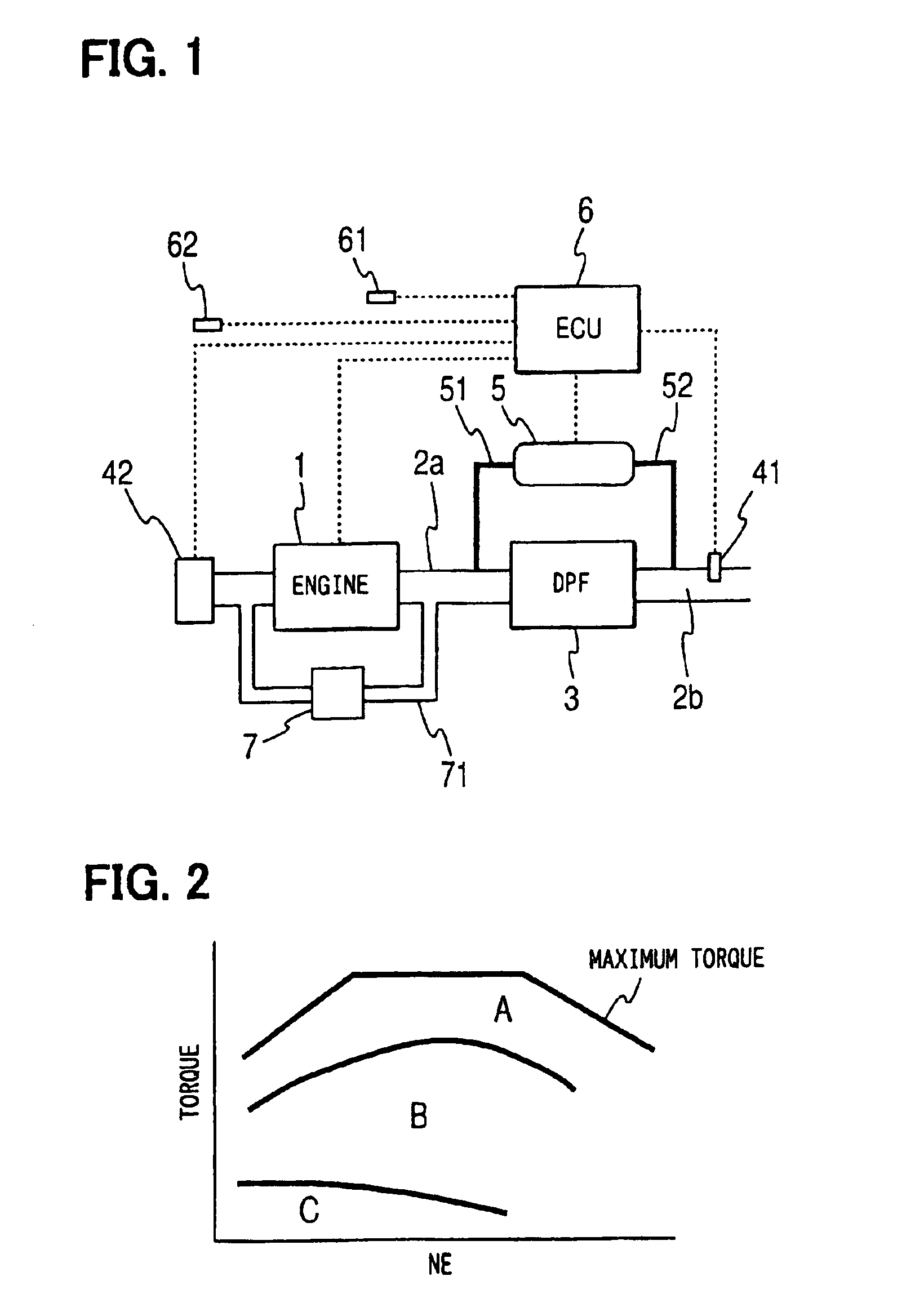
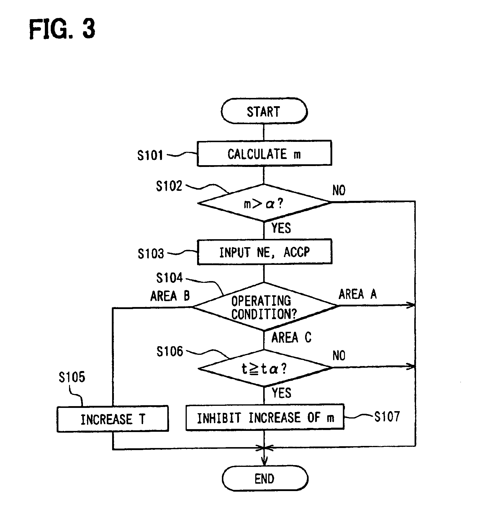
[0014]Even when the regeneration of the particulate filter is required based on the detection result of the particulate matter accumulation quantity detecting means, the regeneration and the like are not performed in the technology of the related art if the operating condition is changed to a low speed and light load condition in which the temperature increase for the regeneration is difficult. Therefore, there is a possibility that the PM accumulation quantity m may increase further and the particulate filter temperature may increase extremely when the regeneration is performed afterward. On the contrary, the particulate matter accumulation inhibiting means of the exhaust gas cleaning system of the present invention is operated to inhibit the accumulation of the particulate matters under the predetermined operating condition. Therefore, the PM accumulation quantity m is not increased virtually. Therefore, the particulate filter can be regenerated safely by performing the temperature increasing operation with the temperature increase controlling means when the regeneration becomes possible afterward. Thus, degradation of engine performance or degradation of a catalyst can be prevented.

Problems solved by technology

Even when the regeneration of the particulate filter is required based on the detection result of the particulate matter accumulation quantity detecting means, the regeneration and the like are not performed in the technology of the related art if the operating condition is changed to a low speed and light load condition in which the temperature increase for the regeneration is difficult.

Method used


Image

  • Exhaust gas cleaning system of internal combustion engine
  • Exhaust gas cleaning system of internal combustion engine
  • Exhaust gas cleaning system of internal combustion engine

Examples


example 1

[0045]As shown in FIG. 4, the PM discharge quantity md increases rapidly if the EGR quantity W of the EGR gas recirculated to the intake air through the EGR passage 71 shown in FIG. 1 exceeds a certain value. Therefore, the EGR quantity W is reduced from a preset quantity W2 to another quantity W1, at which the PM discharge quantity md is relatively small, so as to limit the PM discharge quantity md.

example 2

[0046]As shown in FIG. 5, the PM discharge quantity md increases rapidly if the fuel injection quantity exceeds a certain value. The generation of the particulate matters is progressed when the quantity of the intake air is insufficient with respect to the fuel quantity. Therefore, the upper limit value X of the fuel injection quantity is reduced from a preset value X2 to another value X1 in order to limit the PM discharge quantity md as shown in FIG. 5. Thus, the generation of the particulate matters can be prevented effectively.

example 3

[0047]As shown in FIG. 6, the PM discharge quantity md decreases as the fuel injection pressure Y increases. Therefore, the fuel injection pressure Y is increased from a preset pressure Y2 to another pressure Y1 in order to limit the PM discharge quantity md.


PUM


Abstract

An electronic control unit (an ECU) detects an operating condition of an engine and quantity of particulate matters accumulated in a diesel particulate filter (a DPF) having an oxidation catalyst from a pressure difference across the DPF. The ECU operates temperature increasing means for regenerating the DPF based on the above detection results. During a low speed and light load operation, the ECU does not perform temperature increasing operation similar to an operation performed during a middle load operation. Instead, the ECU performs operation such as reduction of recirculated exhaust gas quantity in order to inhibit an increase in the quantity of the accumulated particulate matters. When the operating condition is changed afterward, the temperature increasing means is operated, so safe regeneration of the DPF is achieved.

Description

CROSS REFERENCE TO RELATED APPLICATION[0001]This application is based on and incorporates herein by reference Japanese Patent Application No. 2002-345463 filed on Nov. 28, 2002.BACKGROUND OF THE INVENTION[0002]1. Field of the Invention[0003]The present invention relates to an exhaust gas cleaning system having a particulate filter for collecting particulate matters included in exhaust gas of an internal combustion engine.[0004]2. Description of Related Art[0005]Particulate matters discharged from a diesel engine have a great effect on the environment. As a countermeasure to it, conventionally, a diesel particulate filter (a DPF, hereafter) formed of a ceramic porous body is employed, for instance. The DPF is disposed in an exhaust pipe in order to collect the particulate matters at its porous partition walls. The DPF is regenerated by eliminating the collected particulate matters through combustion regularly.[0006]In the regeneration of the DPF, a quantity of the accumulated particu...

Claims


Application Information

Patent Timeline
IPC IPC(8): F02D41/00F02D41/02F02D21/00F01N9/00F02D21/08F02M25/07
CPCF02D41/029F02D41/1448F01N9/002F01N2330/06F01N2430/06F01N2430/08F01N2430/085F01N2510/065F02D41/0055F02D41/1446F02D41/187F02D2200/0812F02D2200/602F02M25/0715F02M26/13
Inventor KUBOSHIMA, TSUKASAKINUGAWA, MASUMISEKIGUCHI, KIYONORISAITO, MAKOTOYAHATA, SHIGETO
Owner DENSO CORP
Learn More