Projection type image display apparatus and image display system

a projection optical system and image display technology, applied in the direction of projectors, color television details, instruments, etc., can solve the problems of increasing the size of the lens itself, increasing the distance of the light-emitting position of the organic el element from the optical axis, and high heat produced by light sources, so as to achieve the effect of effectively capturing light emitted and brightening the image without increasing the size and cost of the projection optical system

Inactive Publication Date: 2005-10-04
CANON KK
View PDF8 Cites 77 Cited by
  • Summary
  • Abstract
  • Description
  • Claims
  • Application Information

AI Technical Summary

Benefits of technology

[0027]It is an object of the present invention to provide a projection type image display apparatus capable of effectively capturi...

Problems solved by technology

Therefore, to brighten a displayed image, a metal halide or high-pressure mercury lamp is used as a light source, but there are additional problems that a high voltage needs to be used as a light source voltage and the light source produces high heat.
However, when the actual projection system is constructed, the above-described projection lens having a telecentric characteristic has difficulty in keeping the vignetting factor of the pupil at 100% from the standpoint of the design as the object height from the optical axis, that is, the distance of the light-emitting position of the organic EL element from the optical axis increases.
However, this will increase the size of the lens itself and increase manufacturing cost accordingly.
Therefore, using a projection lens telecentric toward the organic EL element does not necessarily mean effectively projecting light emitted from the organic EL element and displaying a bright image.
Furthermore, when the organic EL element is caused to emit light continuously at high brightness, the brightness deteriorates notably.
There are various causes for this, but one of major causes is that the current supplied to drive the organic EL element produces heat and when this heat is accumulated, the temperature of the element increases, which changes the structure or characteristic of the organic thin film and the luminance efficiency deteriorates gradually.
However, when the organic EL element is used as an image modulation light emission source, if there is no positional correlation between pixels making up the image and the prism layer, direc...

Method used


Image

  • Projection type image display apparatus and image display system
  • Projection type image display apparatus and image display system
  • Projection type image display apparatus and image display system

Examples


embodiment 1

(Embodiment 1)

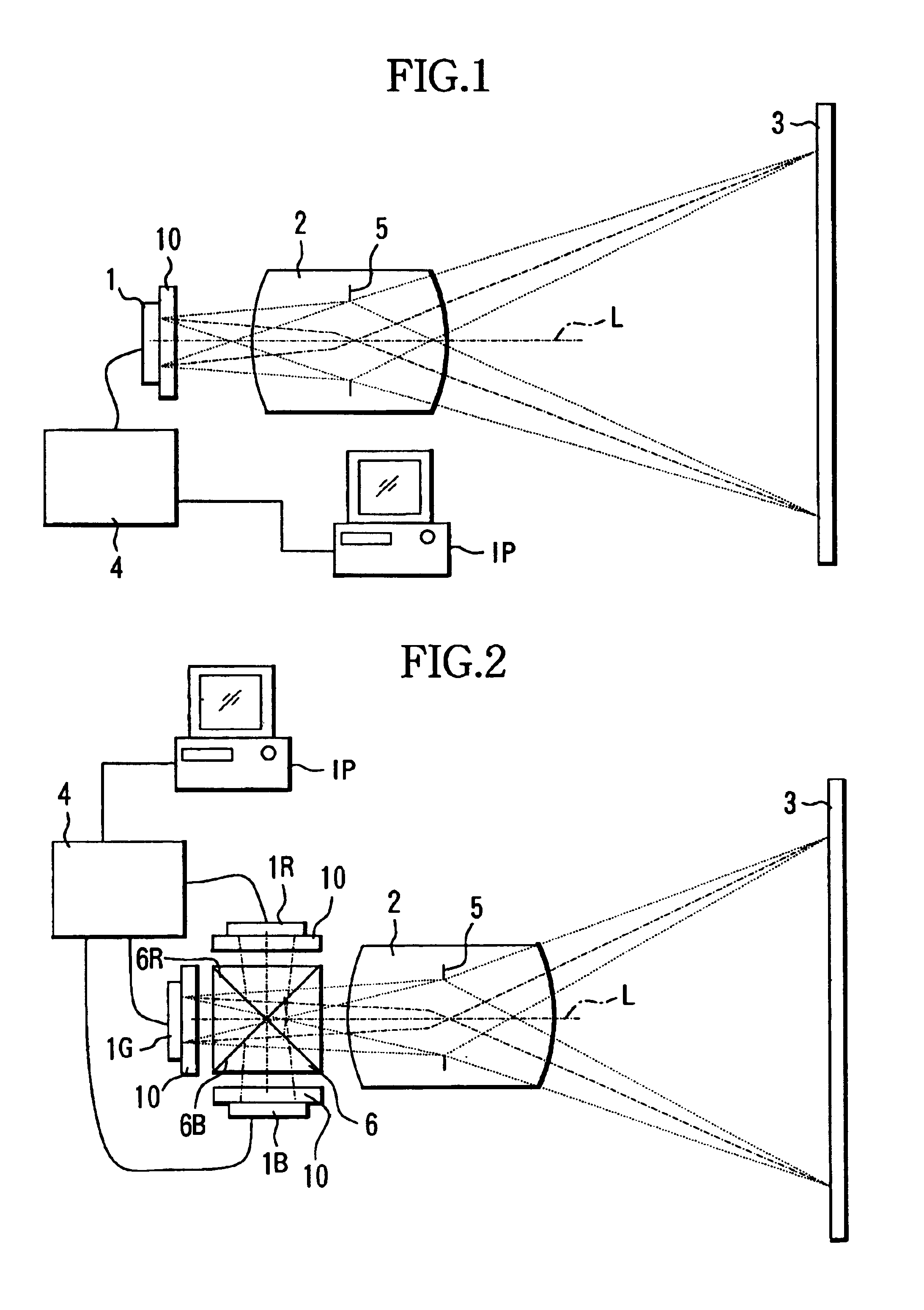
[0062]FIG. 1 is a sectional view of a main optical system of a projector (projection type image display apparatus) which is Embodiment 1 of the present invention.

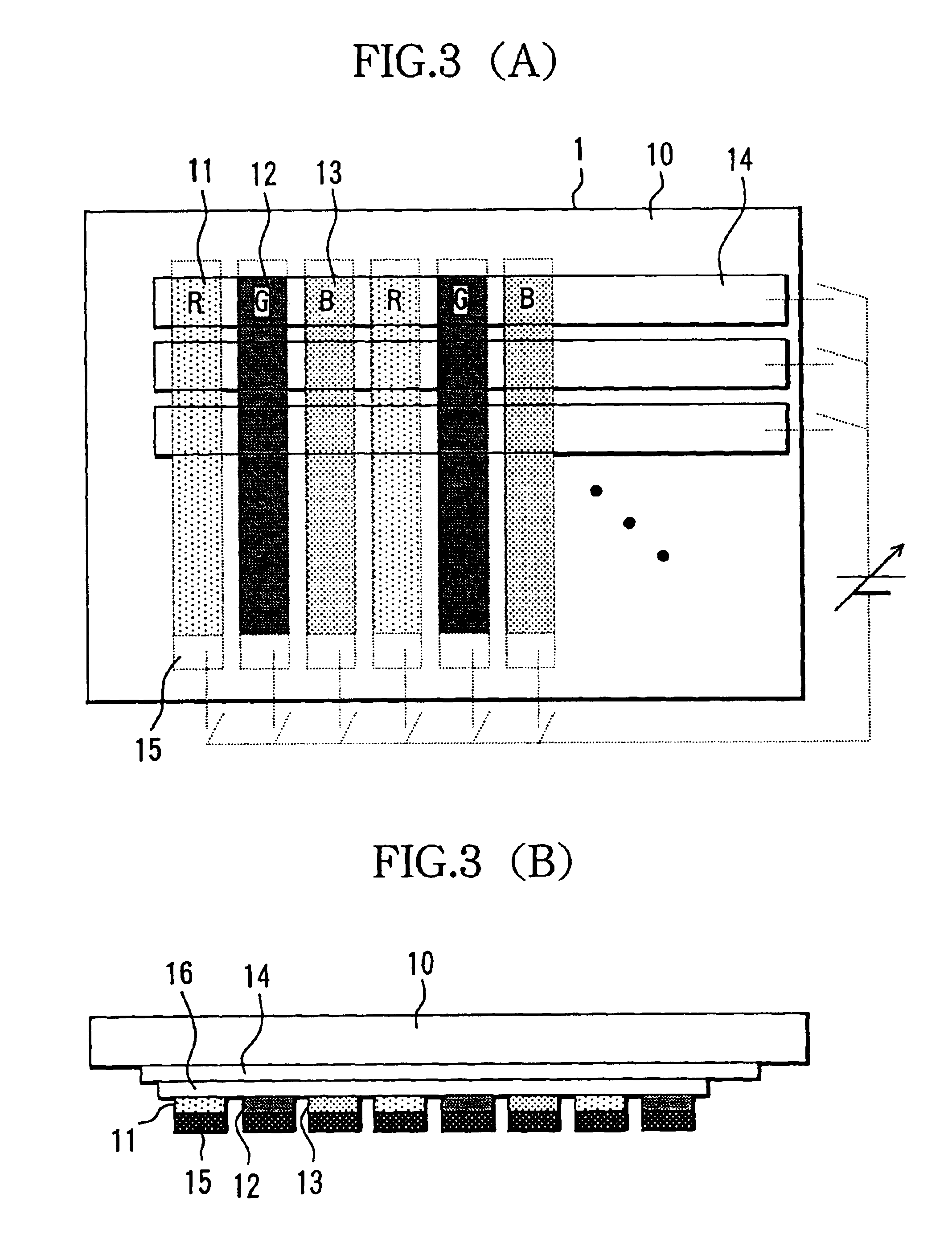
[0063]Reference numeral 1 denotes an electroluminescence (EL) element that emits light including image information and is an organic EL element as will be explained later. This EL element 1 comprises a plurality of pixels that emit light including image information as light pattern information. A detailed structure of this EL element 1 will be explained later.

[0064]Reference numeral 10 denotes a glass substrate that holds a film structure of the EL element 1.

[0065]Reference numeral 4 denotes a controller made up of a CPU, etc., which electrically controls the EL element 1 according to image signals from an image signal providing apparatus IP such as a personal computer, DVD player, VCR, video camera, TV, and unit of an antenna and tuner that receive image signals. The EL element 1 emits light patterned based o...

embodiment 2

(Embodiment 2)

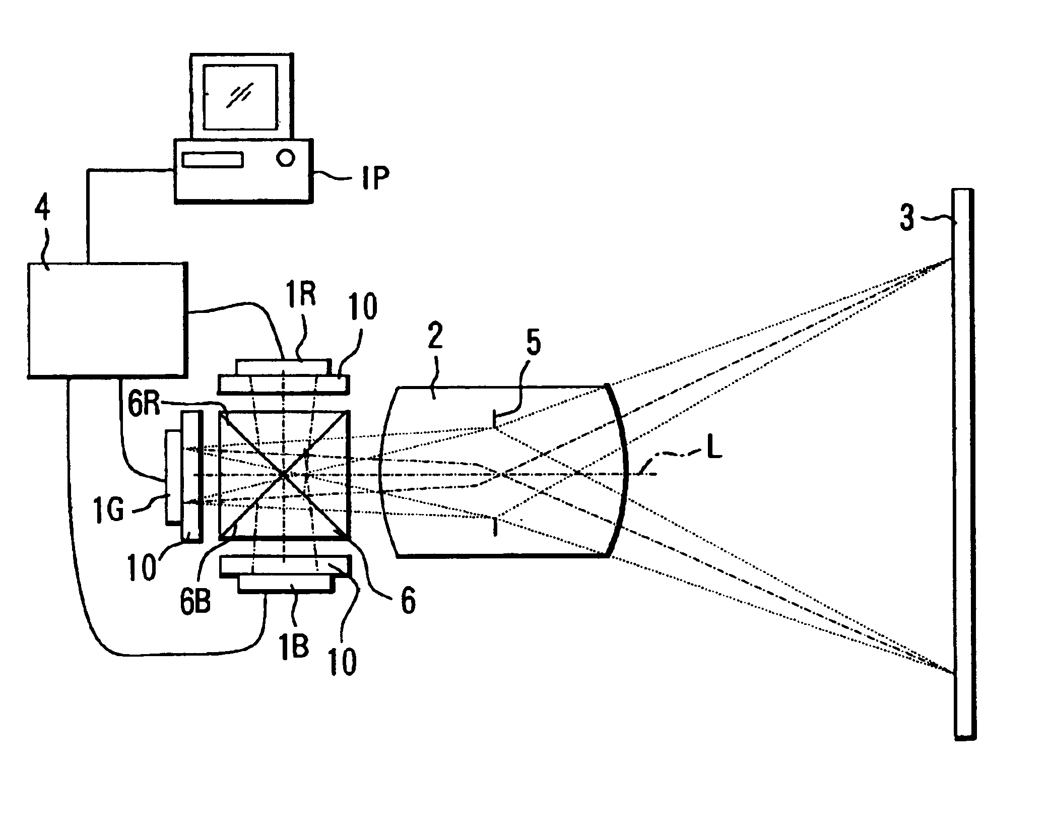
[0069]FIG. 2 is a sectional view of a main optical system of a projector (projection type image display apparatus) which is Embodiment 2 of the present invention.

[0070]Reference characters 1R, 1G and 1B denote EL elements that emit color beams of red, green and blue which are three primary colors for an additive color mixture image, and are organic EL elements in this embodiment as will be described later. Each of these EL elements 1R, 1G and 1B comprises a plurality of pixels which emit light including image information as light pattern information. The controller 4 sends electric signals to the EL elements 1R, 1G and 1B according to image signals input from an image signal providing apparatus IP (the same as described in Embodiment 1) and controls these EL elements 1R, 1G and 1B. The EL elements 1R, 1G and 1B emit color light beams that they handle respectively based on the electric signals from the controller 4. Specific structures of the EL elements 1R, 1G and 1B w...

embodiment 3

(Embodiment 3)

[0135]FIG. 8 is a sectional view of a main optical system of a projector (projection type image display apparatus) which is Embodiment 3 of the present invention.

[0136]Reference numeral 201 denotes an electroluminescence (EL) element that emits light including image information and is an organic EL element in this embodiment as will be described later. This EL element 201 comprises a plurality of pixels that emit light including image information as a light pattern signal. The detailed structure of this EL element 201 will be described later.

[0137]Reference numeral 210 denotes a glass substrate that holds a film structure of the EL element 201. On the electroluminescent film side of the glass substrate 210 is provided a light emission direction control section 205 with two-dimensionally arranged microprism structures as light emission direction control elements.

[0138]Reference numeral 204 denotes a controller made up of a CPU, etc., which electrically controls the EL e...


PUM


Abstract

A projection type image display apparatus includes a projection optical system the projects light emitted from an organic EL element onto a target object. The projection optical system has a characteristic non-telecentric toward the EL element with principal rays which pass through the median point of the aperture pupil that captures light diffusively emitted from the EL element converging when seen from the EL element at a pixel position where the object height on the EL element from the optical axis of the projection optical system reaches a maximum.

Description

BACKGROUND OF THE INVENTION[0001]1. Field of the Invention[0002]The present invention relates to a projection type image display apparatus EL element such as a projector, etc.[0003]2. Description of Related Art[0004]A conventional projection type display normally uses a liquid crystal panel or micromirror device as a light modulation device for switching, projects a light pattern selected by controlling transmission, shielding or deflection of light onto a screen, and thereby displays the image on the screen.[0005]When a liquid crystal panel or micromirror device is used as a light modulation device on the above-described display, it is assumed that shielded light is regarded as unnecessary energy and absorbed by a polarization element or light absorption medium and eliminated. Therefore, to brighten a displayed image, a metal halide or high-pressure mercury lamp is used as a light source, but there are additional problems that a high voltage needs to be used as a light source volta...

Claims


Application Information

Patent Timeline
IPC IPC(8): G03B21/00G02B27/14
CPCG02B27/102G02B27/1086G02B27/149G03B21/00H04N9/3138G03B21/005
Inventor KOIDE, JUN
Owner CANON KK
Why Eureka
Try Eureka