Cemented carbide ball end mill

a technology of cement carbide and end mill, which is applied in the direction of shaping cutters, milling cutters, manufacturing tools, etc., can solve the problems of end mills falling into a state of inability to cut, and achieve the effects of improving machining performance, reducing the number of grinding holes, and ensuring the cutting edge is rigid

Inactive Publication Date: 2005-10-11
NACHI-FUJIKOSHI
View PDF16 Cites 20 Cited by
  • Summary
  • Abstract
  • Description
  • Claims
  • Application Information

AI Technical Summary

Benefits of technology

[0009]With this construction, the cemented carbide ball end mill of the invention is provided with the wide chip evacuating flute to have the excellent chip evacuating performance and the sufficient rigidity of the cutting edge, thereby improving the machining performance for semi-dry and wet machining of an aluminum alloy.
[0010]Further, as claimed in claim 2, the cutting portion of the cemented carbide ball end mill may have a coating formed on the surface the cutting portion. The coating includes a first layer coating film of titanium carbide (TiC) or aluminum titanium nitride (TiAlN) and a second layer coating film which is formed on the first layer coating film and comprises a titanium carbide system film (TiC / C) having a physical property similar to that of diamond, a silicon carbide system amorphous film (SiC / C) having a physical property similar to that of diamond, a chromium carbide system film (CrC / C), or a boron carbide system film (BC / C). With this coating, the semi-dry and wet machining capability of the cemented carbide ball end mill is further improved, and moreover the dry machining is enabled.

Problems solved by technology

This causes a problem that even when a coating film similar to that described above is applied to the ball end mill, chip packing or clogging occurs at the tip of the ball portion and the end mill falls into a state incapable of cutting.

Method used


Image

  • Cemented carbide ball end mill
  • Cemented carbide ball end mill
  • Cemented carbide ball end mill

Examples


Embodiment Construction

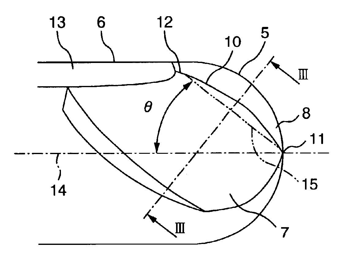
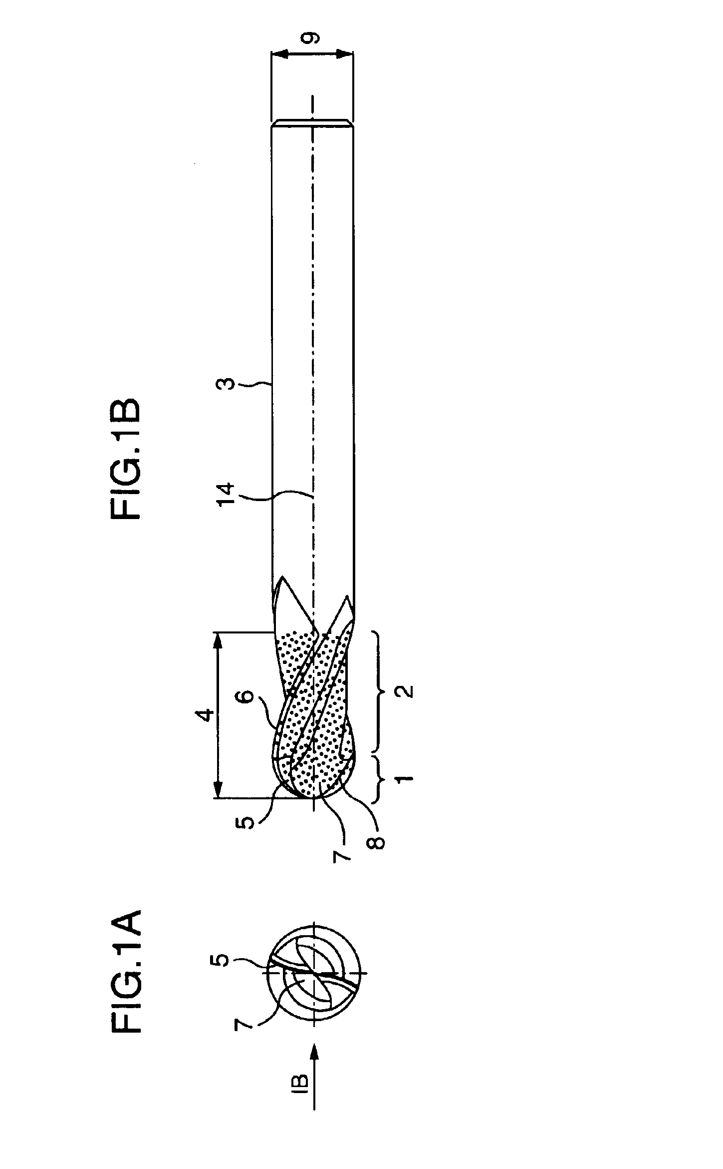
[0021]With reference to the drawings, the cemented carbide ball end mill having two cutting edges according to the embodiment of the present invention will be described.FIG. 1A is a front view of the cemented carbide ball end mill, FIG. 1B is an enlarged side view thereof, and FIG. 2 is a view of the tip portion of the cemented carbide ball end mill as viewed in the direction of an arrow IB shown in FIG. 1.

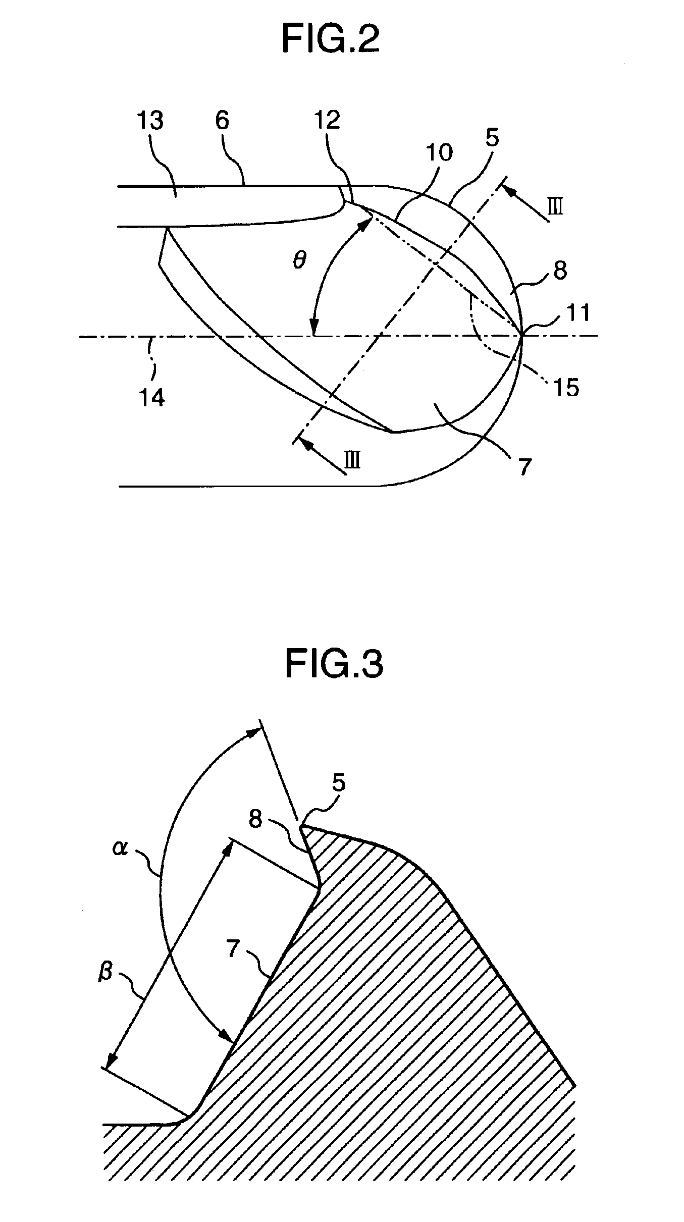
[0022]In FIG. 1B and FIG. 2B, an outer peripheral cutting portion 2 is provided continued to a ball portion 1, and further a bar-shaped shank portion 3 is provided. Cutting edges are formed in the ball portion 1 and the outer peripheral cutting portion 2, and these are cutting edges 5 of the ball portion and cutting edges 6 of the outer peripheral cutting portion. The axial portion provided with the cutting edges forms a cutting portion generally denoted by a reference numeral 4. A chip evacuating flute 7 is formed adjacent to a rake face 8 defining each cutting edge 5.

[0023]In th...


PUM

PropertyMeasurementUnit
angleaaaaaaaaaa
angleaaaaaaaaaa
radiusaaaaaaaaaa

Abstract

A cemented carbide ball end mill comprises a cutting portion with a semi-spherical ball portion at a tip thereof. The cutting edge portion has a cutting edge rake face and a chip evacuating flute at the ball portion. An angle formed by a straight line connecting a vertex of the ball portion, where an intersection line passes through, and another end of the intersection line with respect to the central axis, is from 30° to 50°. Further, and angle formed by the rake face and the chip evacuating flute is from 100° to 150°, and a width of the chip evacuating flute is 0.5 to 5 times as large as a radius of the ball portion.

Description

BACKGROUND OF THE INVENTION[0001]This invention generally relates to a cemented carbide ball end mill for machining an aluminum alloy, and more particularly to an improvement in the configuration of and in a coating film for a cemented carbide ball end mill capable of performing dry machining.[0002]Hitherto, when machining an aluminum alloy with a cemented carbide ball end mill, in order to prevent the melted aluminum alloy from being deposited on the machine tool, the aluminum alloy has usually been machined while applying water-soluble cutting fluid for promoting lubricating action. In recent years, however, because of a corrosive property of the water-soluble cutting fluid or a difficulty in handling of the cutting fluid as industrial waste, demand for machining an aluminum alloy by a cemented carbide ball end mill without using the cutting fluid, or needs for so-called dry machining have been rising.[0003]A problem posed when machining an aluminum alloy with a cemented carbide b...

Claims


Application Information

Patent Timeline
Patent Type & Authority Patents(United States)
IPC IPC(8): B23C5/10B23C5/16
CPCB23C5/1009B23C2210/0421B23C2210/0442B23C2224/28B23C2226/72Y10T407/1964Y10T407/1946Y10T407/1962Y10T407/1948Y10T407/1966Y10T407/27
Inventor IWAMOTO, KENJITSURITANI, YOUSUKE
Owner NACHI-FUJIKOSHI
Why Eureka
Try Eureka