Process and apparatus for treating semiconductor production exhaust gases

a technology for processing and exhaust gases, applied in the direction of separation processes, fluorine, organic chemistry, etc., can solve the problems of high running cost of adsorbent treatment, high cost of treatment of adsorbent, and possible heat generation, so as to achieve low running cost and high removal rate of harmful components

Inactive Publication Date: 2005-10-11
EBARA CORP
View PDF22 Cites 7 Cited by
  • Summary
  • Abstract
  • Description
  • Claims
  • Application Information

AI Technical Summary

Benefits of technology

[0016]It is the object of the present invention to solve the above problems and to provide a process and an apparatus for treating semiconductor production exhaust gases, ch

Problems solved by technology

Generally, they can achieve a high treatment performance and can adjust the concentration of harmful components at the removal outlet to a low concentration acceptable for working circumstances, but have the following problems.(1) It is necessary to replace a solid adsorbent by flesh one whenever it is exhausted, and hence, the running cost thereof is high.(2) In the case of an exhaust gas containing a solid reaction product, blocking may occur at times.(3) Since the used or exhausted adsorbent contains highly concentrated harmful components, the treatment of the adsorbent is time consuming and is very cos

Method used


Image

  • Process and apparatus for treating semiconductor production exhaust gases
  • Process and apparatus for treating semiconductor production exhaust gases
  • Process and apparatus for treating semiconductor production exhaust gases

Examples


example 1

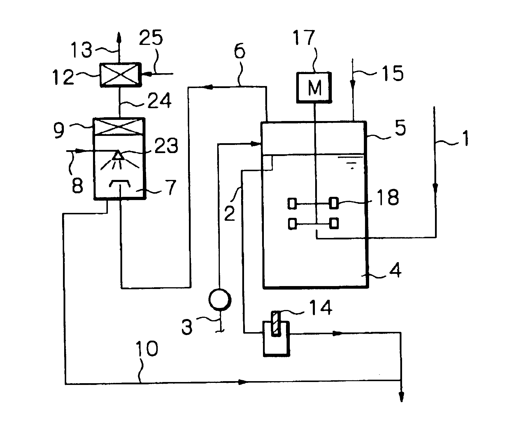
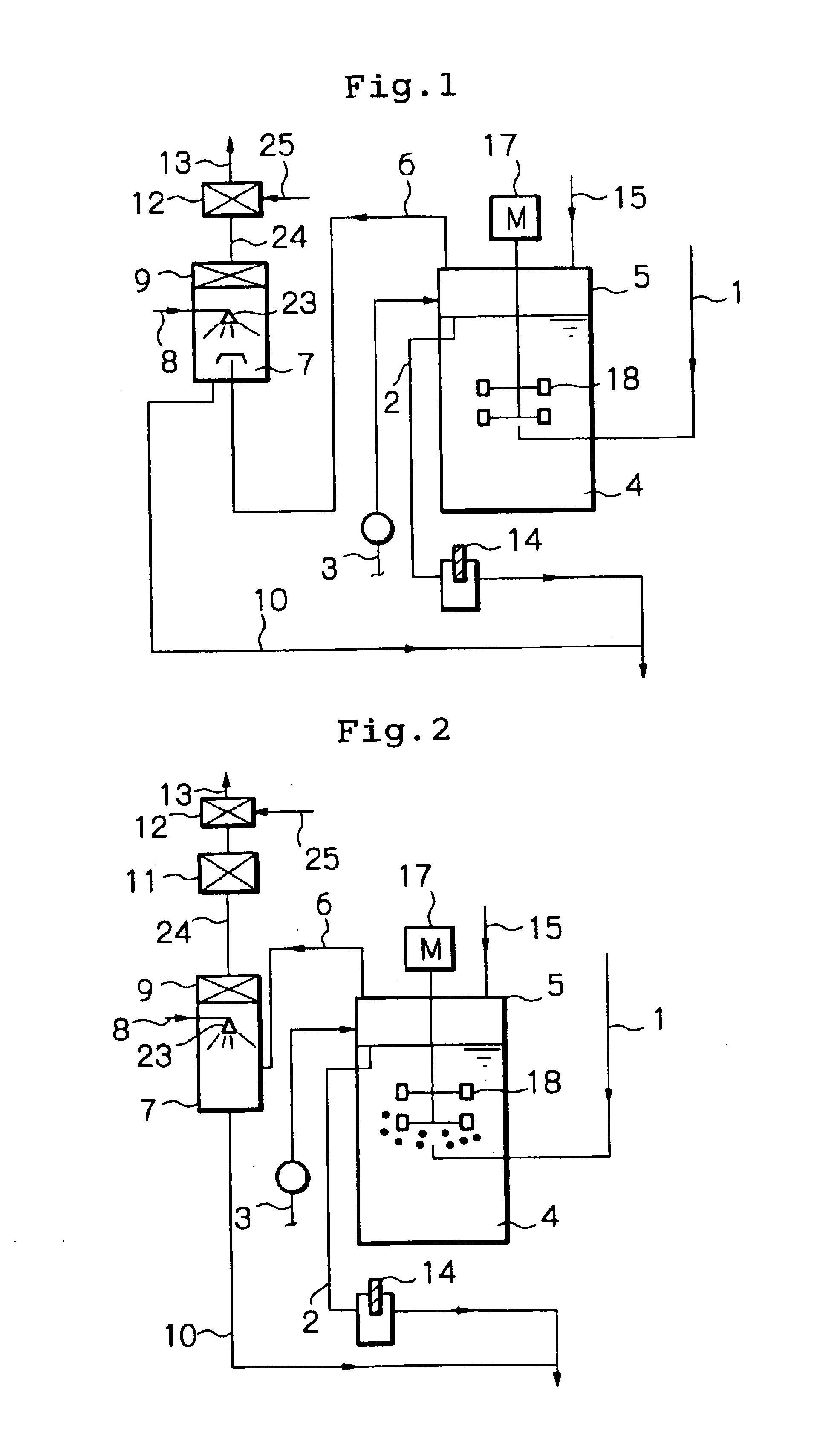
[0077]Employing a treating apparatus shown in FIG. 2, an exhaust gas discharged from an Al etching device for semiconductor production was treated. The flow rate of the semiconductor exhaust gas was 40 l / min.

[0078]The semiconductor exhaust gas 1 was, first of all, introduced into an aeration stirring tank 5 filled with water 4, the pH of which was adjusted to from 8.5 to 9.5 with the addition use of ammonia water 3. The introduced gas was then finely divided by a stirring blade 18 rotated with a motor 17 and came into contact with water 4. The rotation speed of the stirring blade 18 was set at 600 rpm. In order to prevent products from accumulating in the water 4, water 15 was introduced at a rate of 3 l / min into the aeration stirring tank, and the same amount of a blow-down drain 2 was drained. The pH of the blow-down drain was constantly monitored by a pH electrode 14, and the ammonia water 3 was injected when the pH was below 9.

[0079]The aeration stirring tank outlet gas 6 coming...

example 2

[0085]The treatment was conducted continuously for one month, and no trouble such as blocking in the apparatus due to solids contained in the semiconductor exhaust gas and heat release occurred. Moreover, the inside of the duct of the device outlet was checked after completion of the treatment, no adhesion of powders such as B2O3 and NH4Cl was observed.

example 3

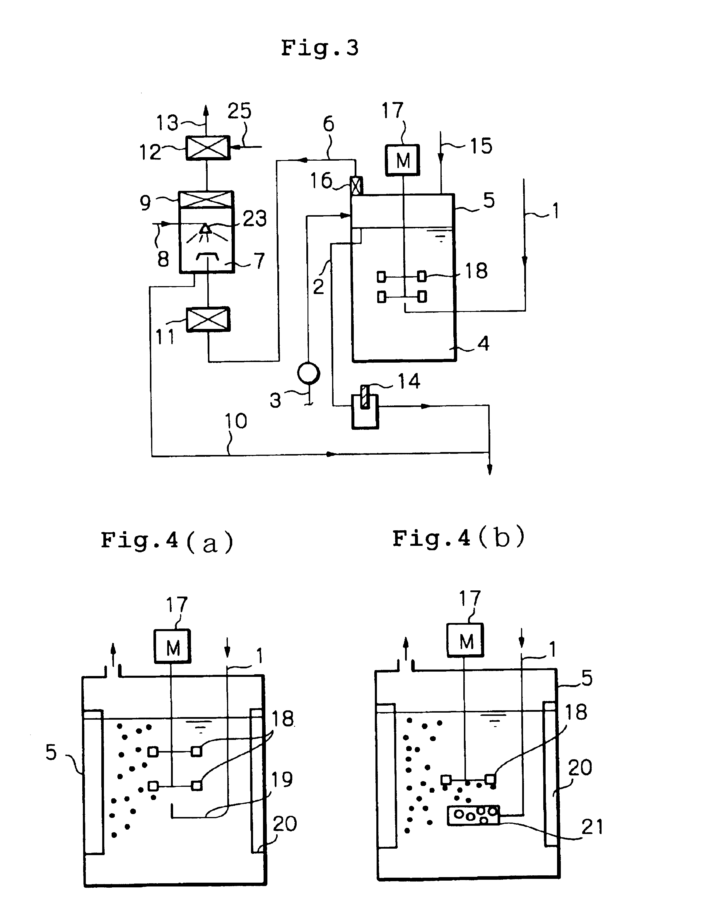
[0086]Changes in the inlet pressure of the apparatus when changing the flow rate of air 25 to be introduced into the air ejector 12 in the constitution as shown in Example 1 are shown in Table 2. As the amount of air introduced increases, the inlet pressure decreases; An introduction of 40 l / min achieved, an inlet pressure of −150 mmAq.

[0087]

TABLE 2Flow rate of air introducedApparatus inletinto air ejector (1 / min)pressure (mmAq)0+60010+30020+10030−5040−150


PUM

PropertyMeasurementUnit
Forceaaaaaaaaaa
Solubility (mass)aaaaaaaaaa

Abstract

A process and an apparatus for treating exhaust gases, comprising an aeration stirring tank (5) employing an aqueous alkaline liquid, and, as a posterior stage, a gas-liquid contact device (7) and/or a packed column (11). The apparatus can remove at the posterior stage harmful gases that the aeration stirring tank fails to remove, for example, water-soluble organic compounds such as ethanol, halogenated silicon compounds such as SiCl4, and halogen gases such as F2 and Cl2. The process and apparatus are particularly suitable for purifying exhaust gases discharged from a semiconductor production device.

Description

[0001]This application is a 371 of PCT / JP98 / 04666 filed Oct. 15, 1998.FIELD TO WHICH THE INVENTION BELONGS[0002]The present invention relates to a treatment of exhaust gases, and in particular, relates to a process and an apparatus for removing harmful components from exhaust gases discharged from a semiconductor production device.PRIOR ARTS[0003]In the present semiconductor production industry, CF4, CHF3, C2F6, Cl2, HBr, HC1, BC13, ClF3 and the like are employed in the processes of dry etching of silicon wafers and chamber cleaning, and tetraethoxysilane (hereinafter referred to as TEOS), NH3, SiH2Cl2 and the like are employed in the CVD process of a silicon wafer. Exhaust gases of these processes include the above unreacted gases, as well as decomposition products such as SiF4, F2, HF, SiCl4, CH3CHO, CH3OH and C2H5OH which exhaust gases cannot be discharged as they are and hence are discharged after harmful components are removed by a removing apparatus.[0004]Removing apparatus ar...

Claims


Application Information

Patent Timeline
IPC IPC(8): B01D53/78B01D53/75B01D53/74B01D53/68
CPCB01D53/68B01D53/75B01D53/78H01L21/02
Inventor IKEDA, HIROSHIKUBOTA, YASUHIROKYOTANI, TAKASHI
Owner EBARA CORP
Why Eureka
Try Eureka