Isolated resonator gyroscope with compact flexures

a gyroscope and compact technology, applied in the field of gyroscopes, can solve the problems of large and heavy, large and heavy, and the mechanism of older conventional gyroscopes was very heavy, and achieve the effect of low total thickness variation

Inactive Publication Date: 2005-10-18
CALIFORNIA INST OF TECH +1
View PDF16 Cites 11 Cited by
  • Summary
  • Abstract
  • Description
  • Claims
  • Application Information

AI Technical Summary

Benefits of technology

[0018]The present invention provides an affordable vibratory gyroscope with navigation grade performance by means of a precision isolated symmetric planar resonator of optimum scale that can be fabricated with silicon photolithography from commercial double-sided polished silicon wafers with low total thickness variation.
[0021]A key element of the present invention is a symmetric double beam flexure arrangement for such an isolated resonator gyroscope which results in reduced reactions to the baseplate. The first and second (e.g., inner) beams of each double beam flexure are attached to the proof mass (e.g., an inner plate portion) and the third and fourth (e.g., outer) beams of each pair are attached to the counterbalancing plate. The symmetry and close radial spacing of the parallel double beams result in comparable (but opposite) moments and forces on each beam element during the counterbalanced rocking motion of the resonator. The convergence of each beam pair into a center beam prior to attachment to the baseplate results in cancellation of moments and forces and a reduced reaction on the baseplate mounting pad. Further, the net sum of these residual reactions from all the beams attached to the baseplate can be nulled by adjustment of the proof mast length (e.g, a vertical post of the proof mass). In addition, the spring constants of the inner versus the outer beams can be independently trimmed or electrostatically modified to provide the desired reactionless counterbalanced rocking motion.

Problems solved by technology

Older conventional gyroscopes were very heavy mechanisms, employing relatively large spinning masses by current standards.
Currently this is often performed with expensive conventional spinning mass gyros (e.g., a Kearfott inertial reference unit) or conventionally-machined hemispherical resonator gyroscopes (e.g. a Litton hemispheric resonator gyroscope inertial reference unit).
However, both of these are very expensive, large and heavy.
This transfer or coupling admits external disturbances and energy loss indistinguishable from inertial rate input and hence leads to sensing errors and drift.
Other planar tuning fork gyroscopes may achieve a degree of isolation of the vibration from the baseplate, however these gyroscopes lack the vibrational symmetry desirable for tuned operation.
In addition, shell mode gyroscopes, such as the hemispherical resonator gyroscope and the vibrating ring gyroscope, are known to have some desirable isolation and vibrational symmetry attributes, however, these designs are not suitable for or have significant limitations with thin planar silicon microfabrication.
The hemispherical resonator employs the extensive cylindrical sides of the hemisphere for sensitive electrostatic sensors and effective actuators, however its high aspect ratio, 3D curved geometry is unsuitable for inexpensive thin planar silicon microfabrication.
The thin ring gyroscope while suitable for planar silicon microfabrication lacks electrostatic sensor and actuators that take advantage of the extensive planar area of the device.
Both effects are undesirable for compact tactical inertial measurement unit (IMU) applications.
Furthermore, the scale of previous silicon microgyroscopes (e.g., U.S. Pat. No. 5,894,090) has not been optimized for navigation grade performance resulting in higher noise and drift than desired.
This problem stems from a use of thin epitaxially grown silicon flexures to define critical vibration frequencies that are limited to 0.1% thickness accuracy.
Consequently device sizes are limited to a few millimeters.
Such designs exhibit high drift due to vibrational asymmetry or unbalance and high rate noise due to lower mass which increases thermal mechanical noise and lower capacitance sensor area which increases rate errors sensor electronics noise.
Scaling up of non-isolated silicon microgyros is also problematic because external energy losses will increase with no improvement in resonator Q and no reduction in case-sensitive drift.
Conventionally machined navigation grade resonators such as in hemispherical or shell gyros have the optimum scale, e.g. 30 mm and 3D manufacturing precision and hence desirable drift and noise performance, however such gyros are expensive and slow to manufacture.
Conventional laser trimming of mechanical resonators can further improve manufacturing precision to some degree, however this process is not suitable for microgyros with narrow mechanical gaps and has limited resolution, necessitating larger electrostatic bias adjustments in the final tuning process.

Method used


Image

  • Isolated resonator gyroscope with compact flexures
  • Isolated resonator gyroscope with compact flexures
  • Isolated resonator gyroscope with compact flexures

Examples


Embodiment Construction

[0034]In the following description, reference is made to the accompanying drawings which form a part hereof, and which is shown, by way of illustration, several embodiments of the present invention. It is understood that other embodiments may be utilized and structural changes may be made without departing from the scope of the present invention.

1.0 Overview

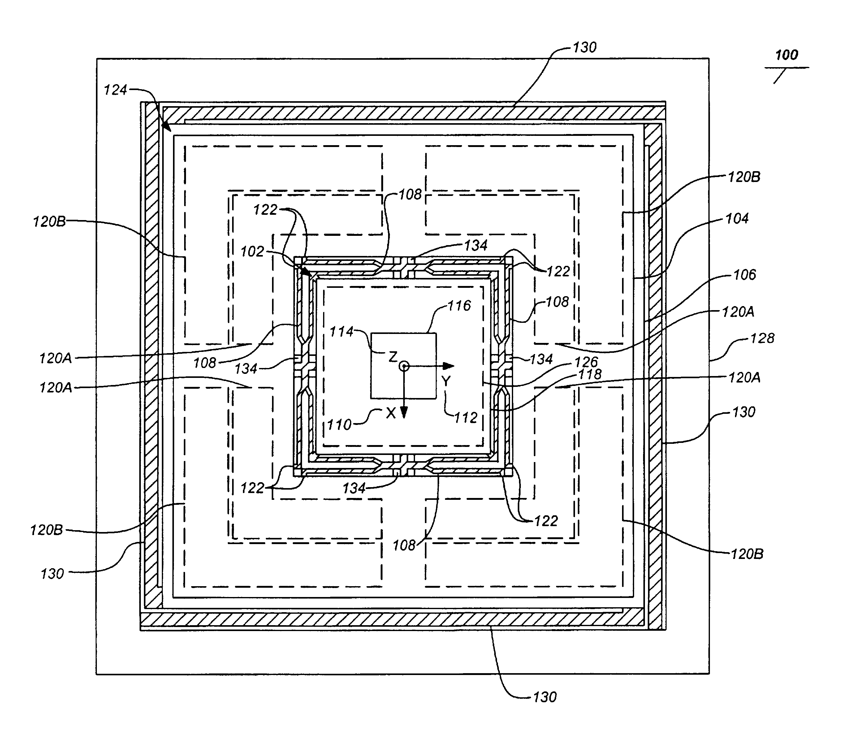
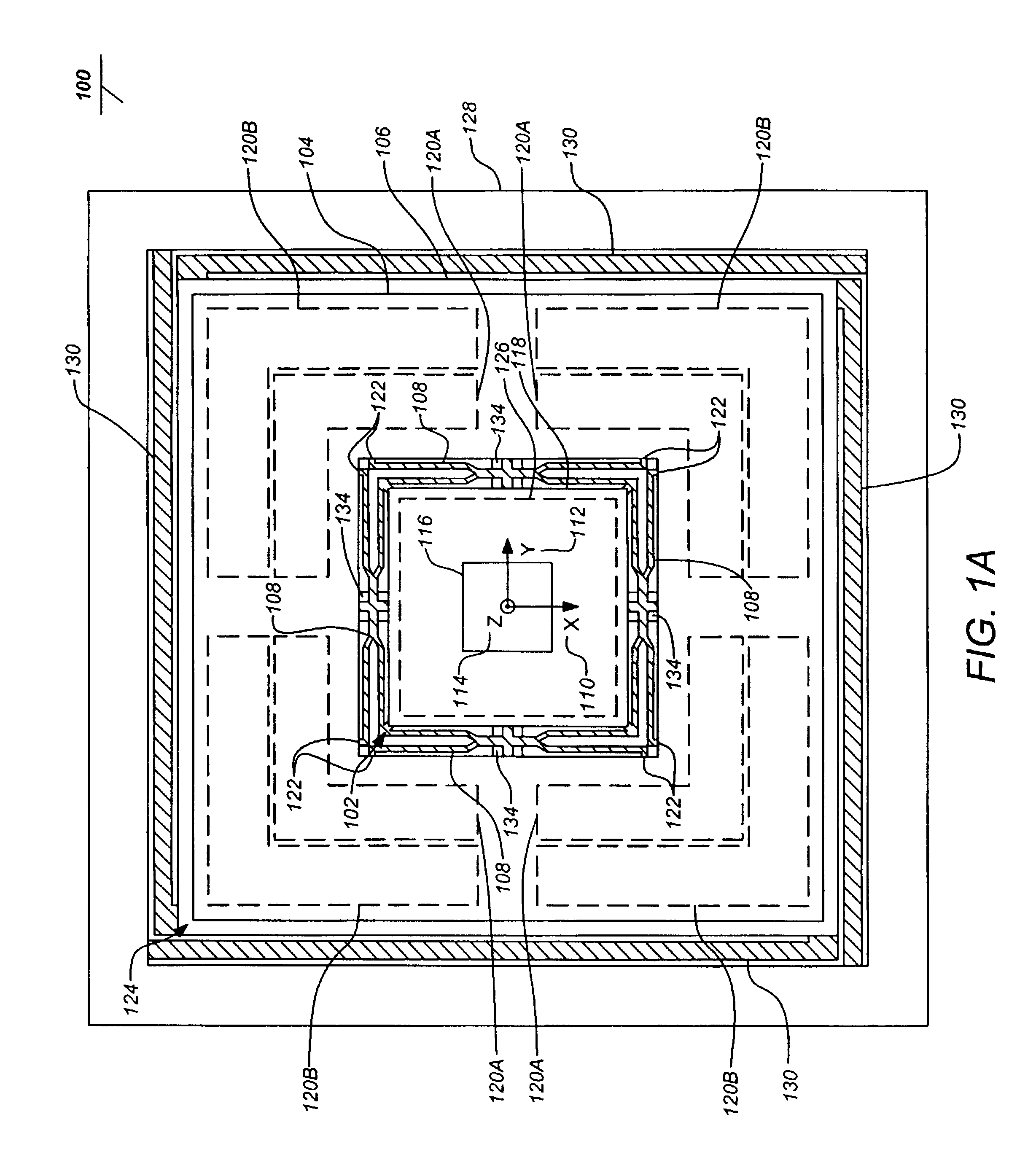
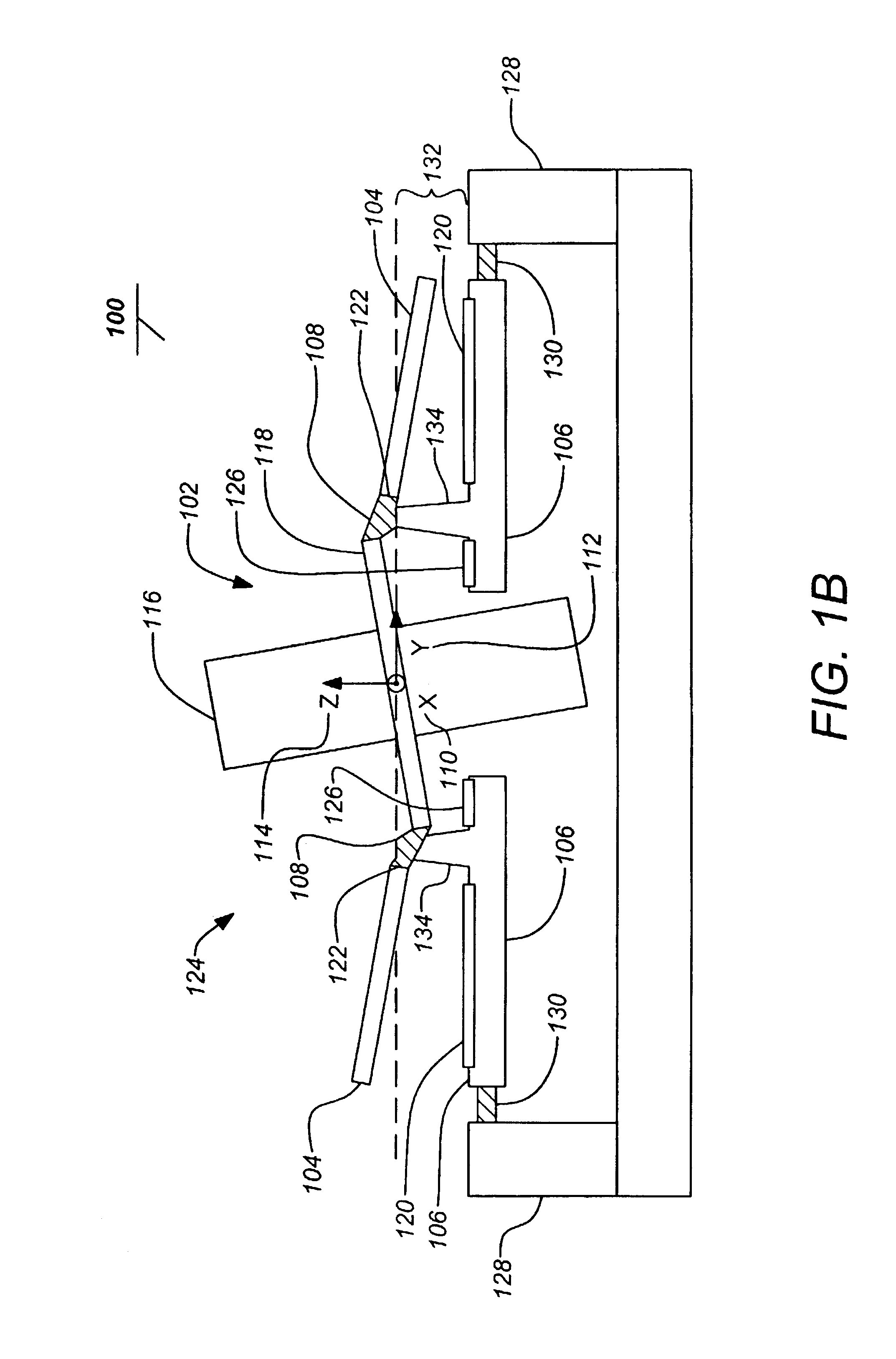
[0035]Embodiments of the present invention generally describe an isolated planar vibratory gyroscope that provides a desired differential rocking mode vibration of a counterbalancing plate versus a central elongated proof mass, while ensuring that the undesirable common rocking mode frequency is practically separated above the desirable differential mode frequency. Embodiments of the invention include isolation that can be simply achieved by adjusting the elongated proof mass (i.e., post) length. The inertias of the proof mass and counterbalancing plate do not have to be as precisely equal.

[0036]Importantly, a double beam flexure...


PUM


Abstract

The present invention discloses a gyroscope comprising an isolated resonator including a post proof mass and counterbalancing plate. One or more double beam flexures each interconnect the counterbalancing plate and the proof mass with a first and a second beam attached to the post proof mass and a third and a fourth beam attached to the counterbalancing plate. A baseplate is affixed to the resonator by the double beam flexures. The counterbalancing plate and the proof mass transfer substantially no net momentum to the baseplate when the resonator is excited.

Description

CROSS-REFERENCE TO RELATED APPLICATIONS[0001]This continuation-in-part application claims the benefit under 35 U.S.C. §120 of the following co-pending and commonly-assigned U.S. utility patent applications, which are all incorporated by reference herein:[0002]U.S. patent application Ser. No. 09 / 928,279, filed Aug. 10, 2001, and entitled “ISOLATED RESONATOR GYROSCOPE”, by A. Dorian Challoner, now U.S. Pat. No. 6,629,460, Issued Oct. 7, 2003; and[0003]U.S. patent application Ser. No. 10 / 370,953, filed Feb. 20, 2003, and entitled “ISOLATED RESONATOR GYROSCOPE WITH A DRIVE AND SENSE PLATE”, by A. Dorian Challoner and Kirill V. Shcheglov.STATEMENT OF GOVERNMENT RIGHTS[0004]This invention was made with Government support awarded by the Government. The Government has certain rights in this invention.BACKGROUND OF THE INVENTION[0005]1. Field of the Invention[0006]The present invention relates to gyroscopes, and in particular to improved resonator microgyroscopes and their manufacture. More ...

Claims


Application Information

Patent Timeline
Patent Type & Authority Patents(United States)
IPC IPC(8): G01C19/56B81B3/00G01P9/04
CPCG01C19/5719G01C19/5712G01P2015/084
Inventor CHALLONER, A. DORIANSHCHEGLOV, KIRILL V.
Owner CALIFORNIA INST OF TECH
Why Eureka
Try Eureka