Tube milling head

a milling head and tube technology, applied in the direction of manufacturing tools, shaping cutters, portable lathes, etc., can solve the problems of limited ability of prior art membrane removal heads to perform tube cleanup and/or weld overlay removal, and occasionally require replacement of tubes, etc., to save downtime and expense, and efficiently complete tube preparation

Inactive Publication Date: 2005-10-18
CLIMAX PORTABLE MACHINE TOOLS
View PDF22 Cites 22 Cited by
  • Summary
  • Abstract
  • Description
  • Claims
  • Application Information

AI Technical Summary

Benefits of technology

[0009]The present invention relates to methods for repair of tubes, especially those used in boiler tube banks. The methods include a tube cleanup step of removing a small or micro-diameter portion or film thickness substantially around the entire circumference of a tube end with a rotary milling device or power tool having a specialized tube film removal milling head. The tube film is removed preferably at least in an area to be beveled, or also in a longitudinal area adjacent an area to be beveled. Advantageously, the film removal milling head is also capable of removing any weld overlay from the surface of a tube. The tube outer circumference film removal step removes a predetermined radial thickness or annulus from the circumference of the outer diameter of the tube. Preferably, the radial film removal provides a substantially bare metal surface. The film removal step provides a tube surface free of rust, scale, etc., and contributes to a stronger weld between adjacent tubes.
[0010]In one embodiment, the method includes the usual step of cutting a worn or damaged section from an existing boiler tube wall to provide an opening in the tube wall having upper and lower horizontal edges transverse to the longitudinal direction of the vertical tubes comprising the tube wall. In accordance with the principles of the invention, the membrane material, if present between adjacent tubes of the boiler tube wall, is removed in the immediate vicinity of the exposed tube ends along the horizontal edges cut into the boiler tube wall by means of a power tool having a rotary milling head which is specially adapted for this purpose. The milling head generally includes a mounting portion at one of its axial ends for attaching it to an arbor or shaft of a rotary power tool, and a plurality of membrane cutting blades generally located at the opposite or distal end of the milling head. The milling head includes an arbor adapted to be inserted into an exposed tube end of an existing boiler tube wall from which a worn or damaged section has been removed. The arbor positions and stabilizes the milling head to prevent movement or jerking of the tool in a direction lateral to the longitudinal direction of the tubes during the milling operation. For membrane removal, each of the plurality of angularly disposed cutting blades has a cutting edge radially displaced from the axis of rotation of the membrane milling head to define an annular cutting sweep having an inner radius which is greater than the nominal outer radius of a tube of the tube wall. The radial thickness (i.e. the difference between the inner and outer circumferences along a line passing through the axis or center of the annular cutting sweep) of the cutting sweep is typically from about ⅜ inch to about ½ inch to allow sufficient clearance for subsequent beveling and welding around the tube ends. The cutting sweep of the blades thereby provides for adequate removal of membrane material from between pairs of adjacent tubes of the tube wall in the vicinity of the tube ends without any risk of damage to, or milling of, the tube wall.
[0013]It is therefore an object of the invention to provide a method including a tube film removal step preferably on an outer portion of a tube, which is useful to prepare or clean a tube for a subsequent welding operation. In one embodiment, the tube film removal cleanup step is performed simultaneously with a weld overlay removal and / or membrane removal step utilizing the same milling head. In a further embodiment, the novel film removal milling head is utilized to remove only weld overlay in addition to any membrane present, without removing substantially any of the tube outer diameter. The tube film removal step provides a beneficial bonding surface without substantially weakening the tube.
[0014]A further object of the invention is to provide a set of milling heads which perform the functions of membrane removal, weld overlay removal, tube end beveling, or a combination thereof, in addition to a tube film removal operation, utilizing the same rotary milling device or power tool. The set of interchangeable milling heads utilizable for tube preparation, useable in conjunction with a single milling device, enables a user to be efficient and thus save downtime as well as expense.
[0015]It is yet another object of the present invention to provide a milling head having blades configured to perform tube film removal, and at least one additional blade or cutting-surface configured to perform a beveling operation on a tube end. In addition, the milling head is adapted to remove any membrane and / or weld overlay present on the tube to a predetermined depth. The milling head allows for precision milling of a tube end wherein the tube surface is prepared for a subsequent welding operation. The milling head capable of performing multiple operations simultaneously enables a user to efficiently complete tube preparation.

Problems solved by technology

On account of deterioration due to corrosion and the like, the tubes occasionally require replacement.
The exposed tube ends of the existing tube wall, however, must be prepared for welding on-site, often in a confined space.
Heretofore, membrane removal utilizing rotary milling tools on an existing tube of a tube wall has been limited to a cutting sweep equal to the outer radius of a tube.
Prior art membrane removal heads are not capable of performing tube cleanup and / or weld overlay removal due to milling head blade configuration or design.
It has been found that beveled tubes joined in this prior manner without diameter cleanup or film removal often have weaknesses at the weld area, occasionally due to pitting, which causes air pockets or lack of weld strength.

Method used


Image

  • Tube milling head
  • Tube milling head
  • Tube milling head

Examples


Embodiment Construction

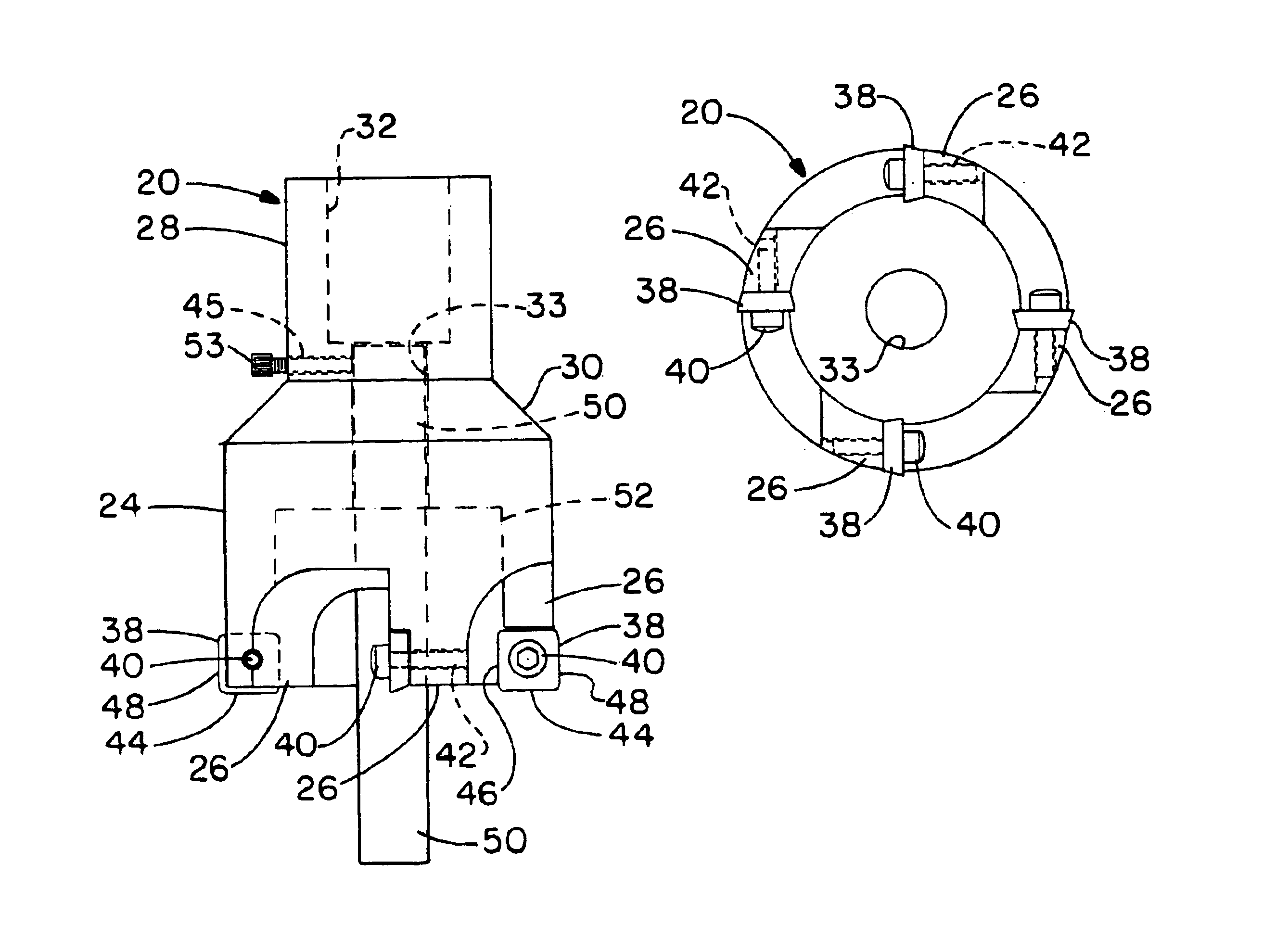
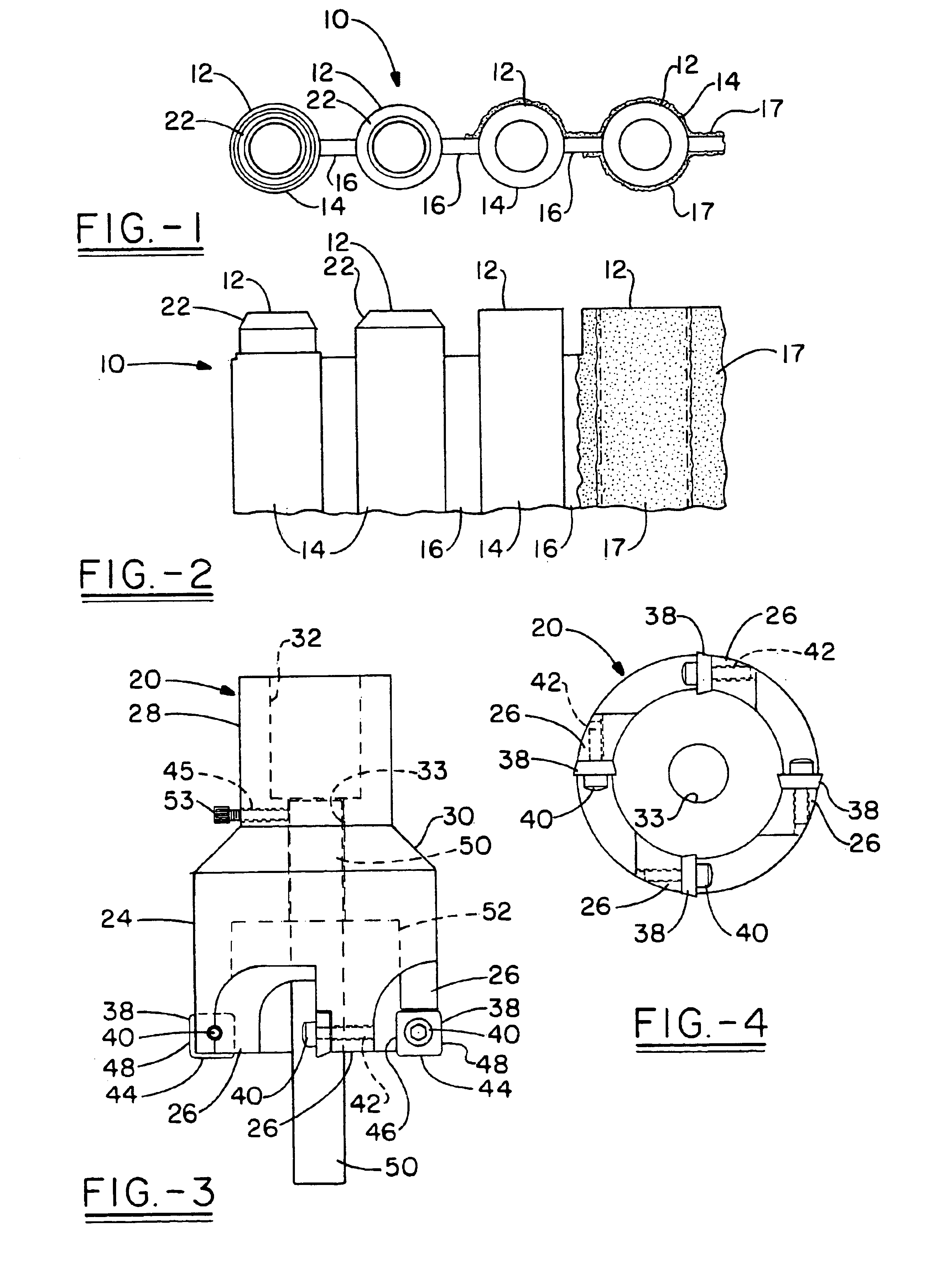
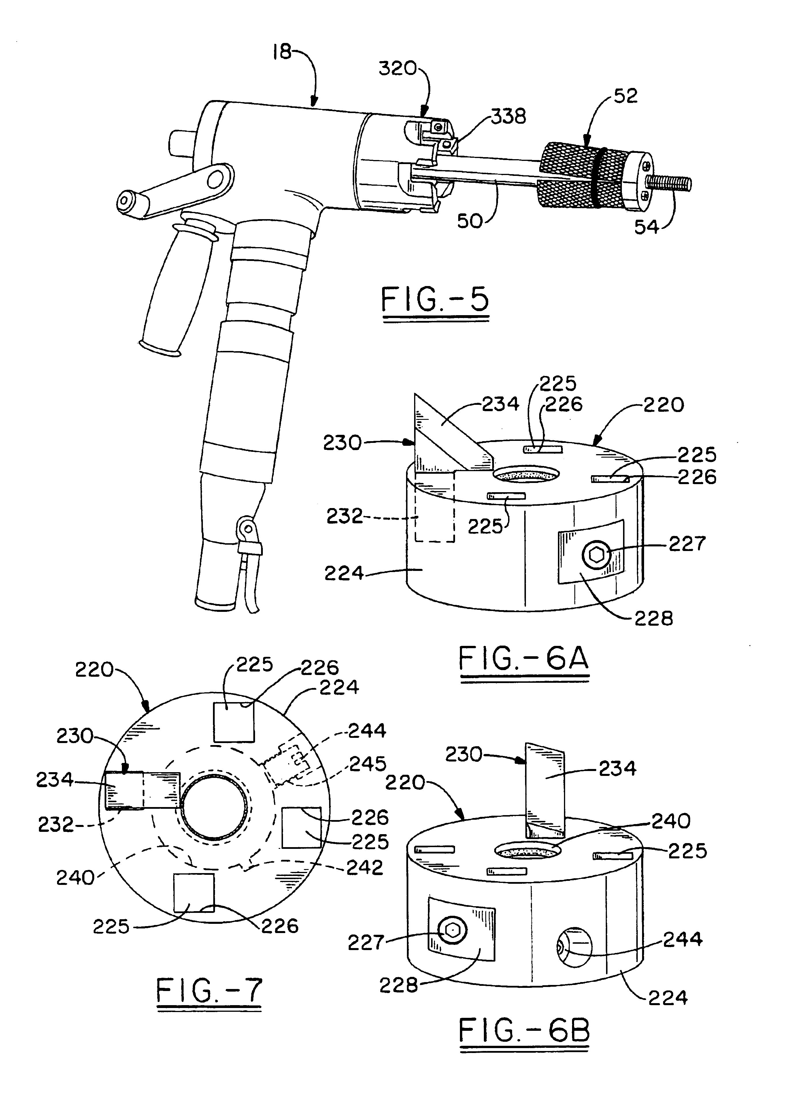
[0031]This description of preferred embodiments is to be read in connection with the accompanying drawings, which are part of the entire written description of this invention. In the description, corresponding reference numbers are used throughout to identify the same or functionally similar elements. Relative terms such as “horizontal,”“vertical,”“up,”“down,”“top” and “bottom” as well as derivatives thereof (e.g., “horizontally,”“downwardly,”“upwardly,” etc.) should be construed to refer to the orientation as then described or as shown in the drawing figure under discussion. These relative terms are for convenience of description and are not intended to require a particular orientation unless specifically stated as such. Terms including “inwardly” versus “outwardly,”“longitudinal” versus “lateral” and the like are to be interpreted relative to one another or relative to an axis of elongation, or an axis or center of rotation, as appropriate. Terms concerning attachments, coupling a...


PUM

PropertyMeasurementUnit
angleaaaaaaaaaa
cutting edge angleaaaaaaaaaa
distanceaaaaaaaaaa

Abstract

Tube ends such as those of boiler tube banks, are prepared utilizing any of various combinations of processes which include a step of micro-diameter tube film removal from a portion of a tube end, including an area below a beveled segment, or segment to be beveled. The micro-diameter film removal step provides the tube with an exposed, clean metal surface which is conducive to a subsequent welding or bonding operation performed on the tube. Preferably, the process is performed with a tube milling tool having interchangeable milling or cutting heads. A specialized milling head is also disclosed and, in one embodiment, is at least used to perform the micro-diameter tube film removal step. Advantageously, the tube film removal milling head also removes a weld overlay on one or both sides of a tube in one embodiment. The tube film removal milling head includes an attached blade having a planar face configuration which enables tube film removal.

Description

CROSS REFERENCE[0001]This application is a continuation-in-part of U.S. Ser. No. 10 / 657,890 filed Sep. 9, 2003 entitled “Method For Tube End Preparation and Milling Head Therefore.”FIELD OF THE INVENTION[0002]Tube ends such as those of boiler tube banks, are prepared utilizing any of various combinations of processes which include a step comprising micro-diameter tube film removal from a portion of a tube end in an area or tube segment to be beveled, and optionally in an area adjacent a segment to be beveled. The micro-diameter film removal step provides the tube with an exposed, clean metal surface which is conducive to a subsequent welding or bonding operation performed on the tube. Preferably, the process is performed with a tube milling tool having interchangeable milling or cutting heads. A specialized milling head is also disclosed and, in one embodiment, is at least used to perform the micro-diameter tube film removal step. Advantageously, the tube film removal milling head a...

Claims


Application Information

Patent Timeline
Patent Type & Authority Patents(United States)
IPC IPC(8): B26D1/01B23C5/00B23C1/00B26D1/12B23B5/16
CPCB23B5/162B23C3/007B23B5/168Y10T407/1946B23B2210/02B23B2226/18B23B2260/124Y10T82/22Y10T407/22Y10T82/16Y10T409/303808Y10T407/1906Y10T407/1936Y10T409/304144Y10T408/8923Y10T408/893Y10T82/16606
Inventor HALL, J. RANDALL
Owner CLIMAX PORTABLE MACHINE TOOLS
Why Eureka
Try Eureka