Method for improving breast cancer diagnosis using mountain-view and contrast-enhancement presentation of mammography

a technology of contrast enhancement and breast cancer diagnosis, applied in image enhancement, instruments, applications, etc., can solve the problems of reducing the efficient use of radiologist's time, not all potentially detectable cancers are reported, and the second reading is expensive and time-consuming. , to achieve the effect of enhancing the contrast of breast images, reducing the number of search misses, and facilitating radiologist detection of breast cancer

Inactive Publication Date: 2005-10-18
CARESTREAM HEALTH INC
View PDF10 Cites 34 Cited by
  • Summary
  • Abstract
  • Description
  • Claims
  • Application Information

AI Technical Summary

Benefits of technology

[0021]The invention provides a general method of enhancing the breast image contrast without adding the edge-banding artifacts around high-contrast edges. The invention has the following advantages.
[0022]1. Produces breast images with an appearance that facilitates radiologist detection of breast cancer thereby helping to reduce the number of search misses.
[0023]2. Enhances the appearance of duct and stroma characteristics in digital mammographic images that facilitates radiologist diagnosis of breast cancer thereby helping to overcome interpretation misses.
[0024]3. Optimal contrast enhancement of an image for visual interpretation is achieved by identifying specifically which image details should be enhanced.
[0025]4. Optimal contrast enhancement of an image for visual interpretation is achieved by determining the degree of enhancement.
[0026]5. The advantages of Xeroradiography are achieved without additional radiation and the messy toner process.

Problems solved by technology

However, due to the limitations of the observers, not all potentially detectable cancers are reported.
However, a second reading is expensive and time consuming.
It reduces the efficient use of a radiologist's time as well as causing delays in patient through-put.
The drawback of these methods is that numerous false positives distract radiologists from the subtle signs of disease not detected by CAD.
Because windowing is applied to one of the segmented image regions, such as uncompressed dense fat and muscle, at the expense of contrast reduction in other segments, a consequence of single scale methods is that the contrast in the area of dense breast tissue is increased at the cost of decreased contrast in the over-penetrated (darker) areas of the image, e.g., near the skin line.
For digital mammograms, this assumption is often invalid because of a strong correlation among neighboring pixels.
Because the initial seed is selected manually, the practical utility of this method is reduced.
The edge-banding artifact is objectionable in areas where there are rapid changes in the image, for example, at the sharp boundaries between the skin line and the air-background in a mammogram.
The second problem is to determine the degree of enhancement.
The methods described in the prior art fail to address these two problems adequately for digital mammography.
First, the amplitude information at each resolution is inadequate to determine whether a large amplitude is caused by a high contrast edge (e.g., from muscle to fat) or an area of interest (e.g., from ducts to fat).
Failure to make the distinction between useful edges and abundant edges will also cause the suppression of fine details associated with high amplitudes, resulting in a loss of important image detail.
Second, a predetermined nonlinear amplitude compression function is not sufficient to adaptively enhance the amount of image detail for each resolution at different spatial locations.
The major disadvantages of xerography are: (1) more radiation by a large factor; (2) messy (due to toner process); (3) more expensive.

Method used


Image

  • Method for improving breast cancer diagnosis using mountain-view and contrast-enhancement presentation of mammography
  • Method for improving breast cancer diagnosis using mountain-view and contrast-enhancement presentation of mammography
  • Method for improving breast cancer diagnosis using mountain-view and contrast-enhancement presentation of mammography

Examples


first embodiment

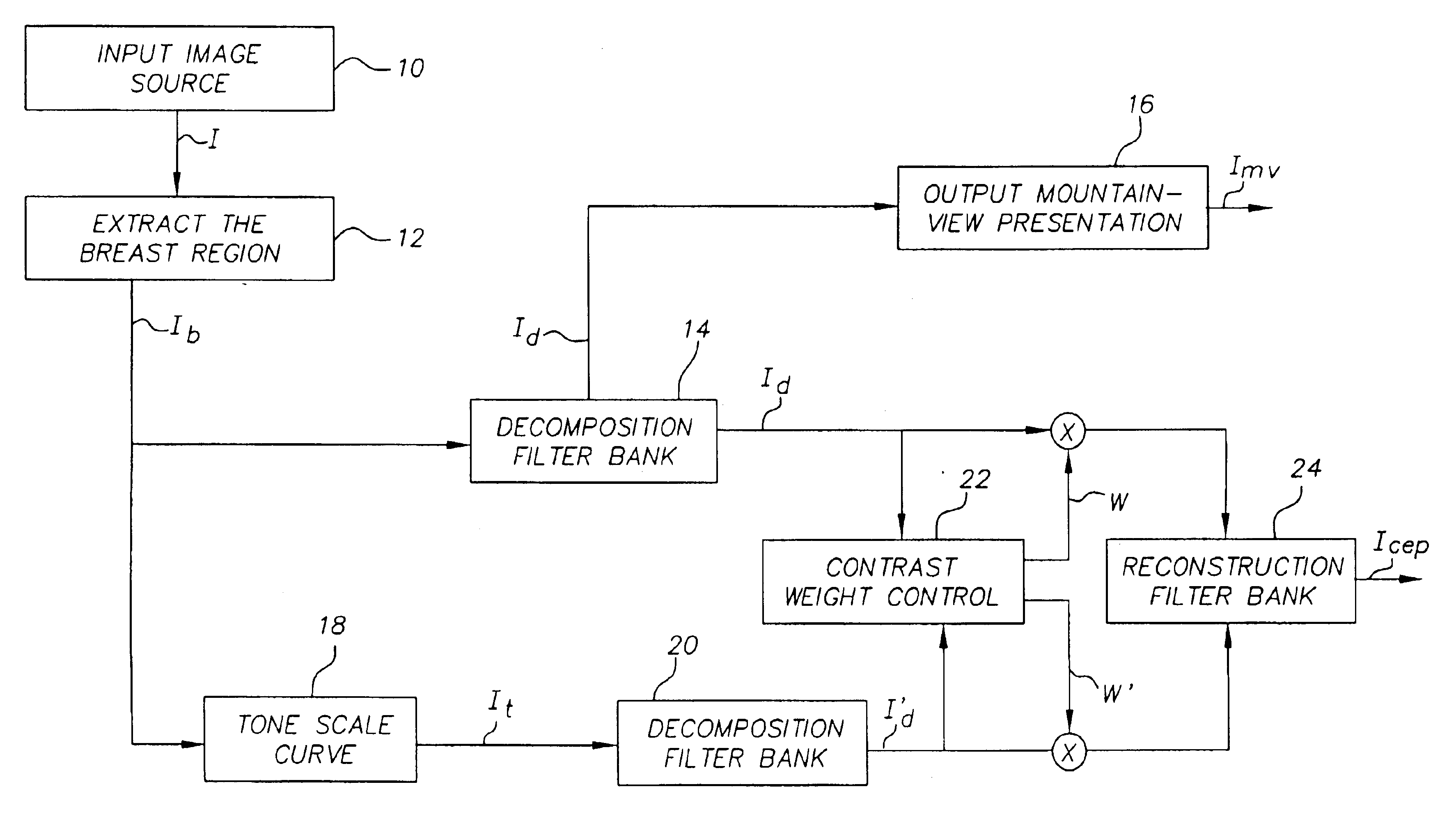
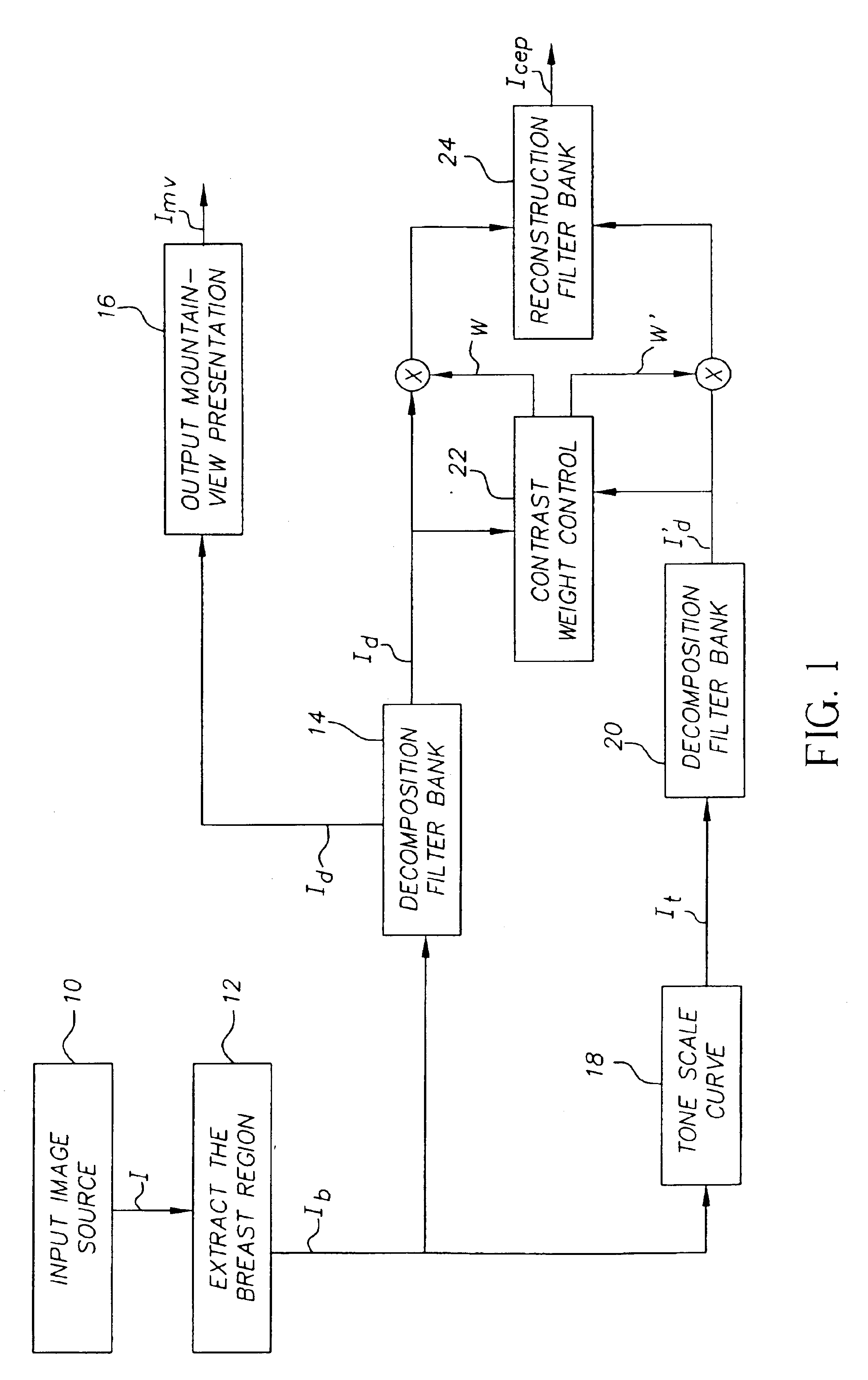
[0059]The invention as shown in FIG. 1 can be performed more efficiently by two different embodiments shown in FIGS. 7a and 7b. Instead of processing the original version of the input image and its tone-scaled version through the decomposition filter bank separately, the new embodiments only process one of the versions and the coarsest scale of the other version. FIG. 7a shows the first embodiment where the preprocessed image Ib is processed in the tone scale curve algorithm 50 to produce a tone-scaled image It. The tone-scaled image is then passed through a filter UN / 2 52 to produce the coarsest scale BN / 2,t. The preprocessed input image Ib, in another pass, is passed through a filter bank, consisting of a set of N decomposition filters F1, F2, . . . , FN, 541, 542, . . . , 54n. The main function of the filters 541-54n in this invention is to extract the image edge features, which are considered as desirable targets for enhancement. The output I1, I2, . . . , IN from each of the fi...

second embodiment

[0060]FIG. 7b shows the The preprocessed input image Ib is passed through two filters FN-1 and FN, 70, 72 to produce the coarsest edge signals, IN-1 and IN respectively. In a parallel path, the preprocessed image Ib is processed in the tone scale curve algorithm 74 to produce a tone-scaled image It. Then, the tone-scaled image is passed through a filter bank, consisting of a set of N decomposition filters F1, F2, . . . , FN, 761-76n, and one low pass filter UN / 2 78. The tone-scaled version output It1, It2, . . . , ItN from the filter bank is modulated in modulators in M1, M2, . . . , MN 801-80n by a gain-control signal G1-Gn, which is produced by the contrast weight control generator. The contrast weight control generator 82 in this embodiment is generated from all the output of the decomposition filter bank of the tone-scaled image It1-ItN as well as the output of coarsest scale of the original image Ib, IN-1, IN. Then the gain-adjusted signals I′t1, I′t2, . . . , I′tN, together w...


PUM


Abstract

A method for improving disease diagnosis using contrast enhancement presentation comprising: providing an input digital diagnostic image; applying a decomposition filter bank to the input digital diagnostic image; constructing a tone scale curve from the input digital diagnostic image; applying said tone scale curve to the input digital diagnostic image to produce a tone-scaled image; applying a decomposition filter bank to the tone-scaled image; generating the contrast weight control signals from the input digital diagnostic image by extracting the high contrast edge signals at the coarse scale; adjusting the decomposition outputs from both the input image and the tone-scaled image according to the contrast weight control signals; and applying a reconstruction filter bank to the adjusted signals to produce a contrast enhancement presentation output image.

Description

FIELD OF THE INVENTION[0001]This invention relates in general to a method for presenting image details in a digital image, and more particularly to a method for presenting diagnostically important image details in digital mammography.BACKGROUND OF THE INVENTION[0002]Breast cancer screening using mammography has demonstrated that early detection is one obvious way to increase survival. However, due to the limitations of the observers, not all potentially detectable cancers are reported. Studies (see C. J. Baines, D. V. McFarlane, and A. B. Miller, “The role of the reference radiologist: estimates of interobserver agreement and potential delay in cancer detection in the national cancer screening study,”Invest Radiology, 25, pp. 971-976, 1990; R. E. Bird, T. W. Wallace, and B. C. Yankaskas, “Analysis of cancers missed at screening mammography,”Radiology, 184, pp. 613-617, 1992; J. A. Harvey, L. L. Fajardo, and C. A. Innis, “Previous mammograms in patients with impalpable breast carcino...

Claims


Application Information

Patent Timeline
Patent Type & Authority Patents(United States)
IPC IPC(8): G06T5/40G06T5/00G06T1/00A61B6/00G06T5/20
CPCG06T5/004G06T5/009G06T5/40G06T7/0083G06T2207/10116G06T2207/20016G06T2207/20132G06T2207/30068G06T7/12
Inventor YOUNG, SUSAN S.
Owner CARESTREAM HEALTH INC
Why Eureka
Try Eureka