Semiconductor wafer inspection system

a technology of semiconductors and inspection systems, applied in semiconductor/solid-state device testing/measurement, mechanical roughness/irregularity measurements, instruments, etc., can solve problems such as improper processing, improper processing, and use of processing chemicals, so as to avoid time and expense of cleaning wafers

Inactive Publication Date: 2005-10-18
QCEPT INVESTMENTS LLC
View PDF62 Cites 15 Cited by
  • Summary
  • Abstract
  • Description
  • Claims
  • Application Information

AI Technical Summary

Benefits of technology

[0023]It is also an object of the invention to provide an improved method and system for rapidly scanning the surface of a semiconductor wafer to identify sub-microscopic, microscopic and macroscopic surface defects characterized by potential field disturbances on the wafer surface.
[0024]It is al

Problems solved by technology

Contamination can arise from use of processing chemicals, processing equipment and poor handling techniques.
Other types of defects can result from a wide range of causes, including flaws in the semiconductor crystal, improper processing, improper handling, and defective materials.
Each step is time consuming and requires expensive chemicals that may require special disposal procedures.
Existing methods for monitoring or controlling these processes are expensive and time consuming.
In addition, many of these analytical techniques are destructive, which requires either the sacrifice of a production wafer or the use of expensive “monitor” wafers for analysis.
Because the number of steps, and period of time, involved in wafer fabrication are so large, a lot of work in process can exist at any point in time.
Many types of defects and contamination are not detectable using existing in-line tools, and these are typically detected and analyzed using expensive and time-consuming “off line” techniques (described below) such as Total Reflectance X-ray Fluorescence (TXRF), Vapor Phase Decomposition Inductively Coupled Plasma

Method used


Image

  • Semiconductor wafer inspection system
  • Semiconductor wafer inspection system
  • Semiconductor wafer inspection system

Examples


example

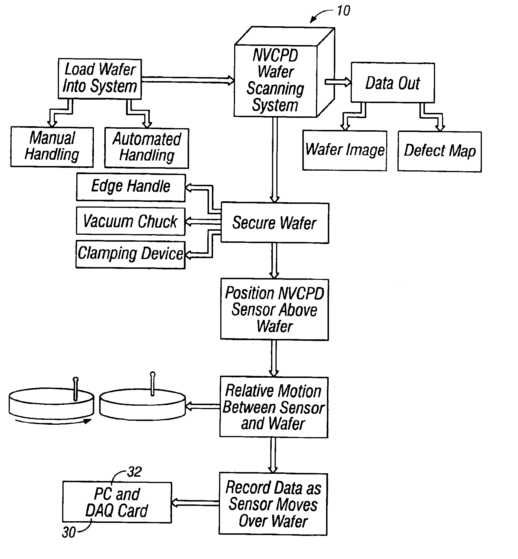
[0062]Sample wafers can be created by dip coating the wafer 15 in solutions that contain known concentrations of contaminants. Part of this example describes metal contaminants such as Cu and Fe, although any manner of chemical contaminants can be applied in this way. The wafer 15 described is either a 100 mm or 150 mm wafer, although these examples apply to any size wafer. The wafer surface 16 is prepared by dipping in HF to remove oxides. The wafer 15 is then cleaned and partially dipped in the metal contaminant solution. The amount of solution remaining on the wafer 15, and the resulting concentration of contaminant on the wafer surface 16, is controlled by selecting dip coating parameters such as the extraction rate.

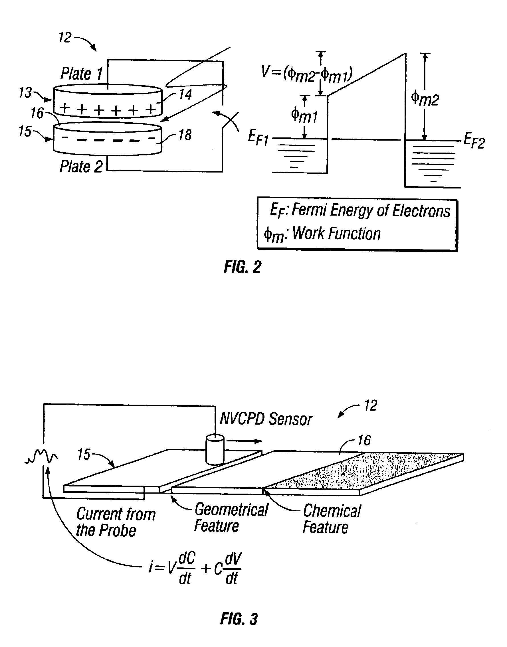
[0063]Partial dipping of the test wafer 15 is preferred to create a transition from clean to contaminated areas. Because the NVCPD signal is differential, the NVCPD sensor 12 detects changes on the wafer surface 16, as opposed to an absolute value relating to surface...


PUM

PropertyMeasurementUnit
Lengthaaaaaaaaaa
Defectsaaaaaaaaaa

Abstract

A method and system for identifying a defect or contamination on a surface of a material. The method and system involves providing a material, such as a semiconductor wafer, using a non-vibrating contact potential difference sensor to scan the wafer, generate contact potential difference data and processing that data to identify a pattern characteristic of the defect or contamination.

Description

[0001]This application claims priority to U.S. application Ser. No. 60 / 444,504, filed on Feb. 3, 2003.[0002]The present invention is directed to a method and system for inspection of semiconductor wafers and other materials. More particularly, the invention is directed to a method and system for characterization of microscopic and macroscopic defects through imaging and visualization of contact potential difference topology on a wafer or material surface through use of a non-vibrating contact potential difference (hereinafter NVCPD) sensor.BACKGROUND OF THE INVENTION[0003]The multi-billion dollar global market for semiconductor defect management is growing both in absolute terms and as a percentage of semiconductor capital equipment investment. In general, there are two factors that determine the economics of a semiconductor fabrication facility at a given utilization level, namely throughput and yield. As complex new technologies such as 300 mm wafers, copper interconnects, and red...

Claims


Application Information

Patent Timeline
IPC IPC(8): G01N27/00G01N33/00
CPCG01N27/002G01N2033/0095G01N27/00G01Q60/48H01L22/00
Inventor STEELE, M. BRANDONHAWTHORNE, JEFFREY ALAN
Owner QCEPT INVESTMENTS LLC
Why Eureka
Try Eureka