Impact resistant structure for the helicopter and energy absorber used for the same

a technology of energy absorber and impact resistance, which is applied in the direction of shock absorbers, elastic dampers, machine supports, etc., can solve the problems of ineffective utilization of sub-floor effective stroke, insufficient floor acceleration reduction, and inability to achieve sufficient floor acceleration reduction, so as to reduce harmful initial load peak level, improve energy absorption property due to axial compression failure, and high performance

Inactive Publication Date: 2005-11-01
KAWASAKI HEAVY IND LTD
View PDF33 Cites 63 Cited by
  • Summary
  • Abstract
  • Description
  • Claims
  • Application Information

AI Technical Summary

Benefits of technology

[0011]Therefore, an object of the present invention is to provide an impact resistant structure of a helicopter, i.e., for a helicopter of which landing gear such as retracted one may not be effectively functioned in crash situation, to provide a fuselage structure having impact absorption capacity against the actual crash environment while providing in a shape fitting to the actual helicopter fuselage structure. Another object of the present invention is to provide a light weight energy high performance absorber in which the harmful initial load peak level is reduced, and in which the energy absorption property due to axial compression failure is improved, also which is able to apply not only to the impact resistant structure of a helicopter but also to the impact resistant structure for general industrial purpose, and which have a desired impact absorption capacity in a shape fitting to the actual helicopter fuselage structure, furthermore in which the effective stroke is increased.

Problems solved by technology

Then, there is always a risk of accident due to contact with an obstacle.
“Full-Scale Crash Test of the Sikorsky Advanced Composite Airframe Program Helicopter” Richard L. Botinott, AHS 56th), the web intersection part X is hard to be crushed, and the sub-floor effective stroke is not effectively utilized, so that a sufficient floor acceleration reduction is not realized.
However, to reduce an impact load by a long absorption stroke, and simultaneously, to realize high impact energy absorption of the merit of a fiber reinforced composite material tube without instability of overall general buckling, if the section of the single tube is simply made larger, the local buckling tendency of the tube wall will be increased and the stable progressive failure mode suitable for impact energy absorption of fiber reinforced composite tube shown in FIG. 20 cannot be achieved.
Further, when a foaming material is filled in all the sections, a space for releasing destroyed small pieces of the composite material generated in the progressive failure mode is lost, and the destroyed small pieces are compacted, and the energy absorber will become extremely stiffened.
Thereby, the effective stroke is reduced, and a required impact absorption capability is not obtained.
Further, to reduce the local unstable buckling of the tube wall, when the section size of the tube is made compact, the aspect ratio (energy absorber height / section width) of whole the energy absorber becomes long and slim, and the energy absorber becomes weak for bending and eccentric compression, so a desired axial compression energy absorption property cannot be achieved.
As a solution for these problems, when the section of the tube is made compact, and is made into a bundling shape, when the number of tubes is optionally adjusted, the number of intersections between stiff walls increases as the number of tubes increases, so that as shown in FIG. 21, the initial load peak level harmful for the impact absorption property increases.

Method used


Image

  • Impact resistant structure for the helicopter and energy absorber used for the same
  • Impact resistant structure for the helicopter and energy absorber used for the same
  • Impact resistant structure for the helicopter and energy absorber used for the same

Examples


Embodiment Construction

[0051]An impact resistant structure for the helicopter of an embodiment of the present invention and an energy absorber of an embodiment of the present invention used in the same will be explained below with reference to the accompanying drawings.

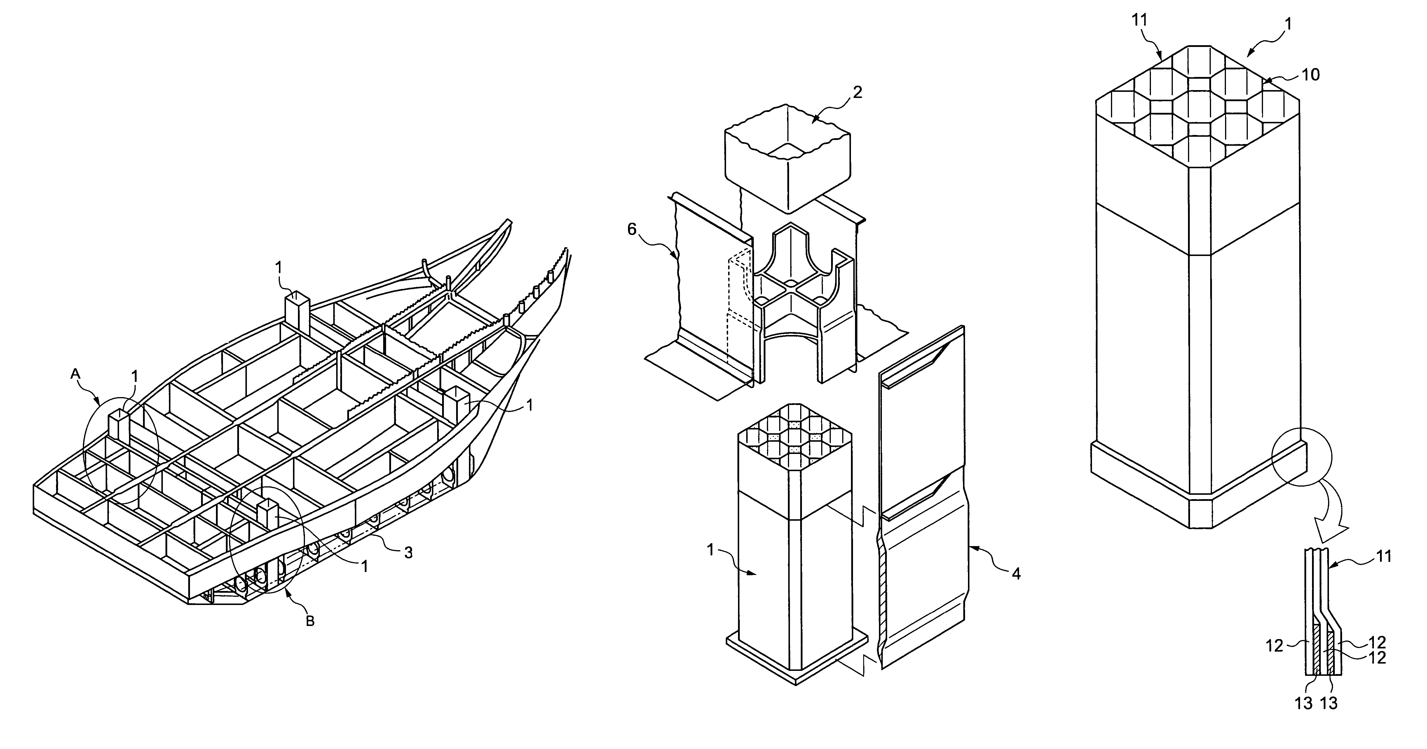
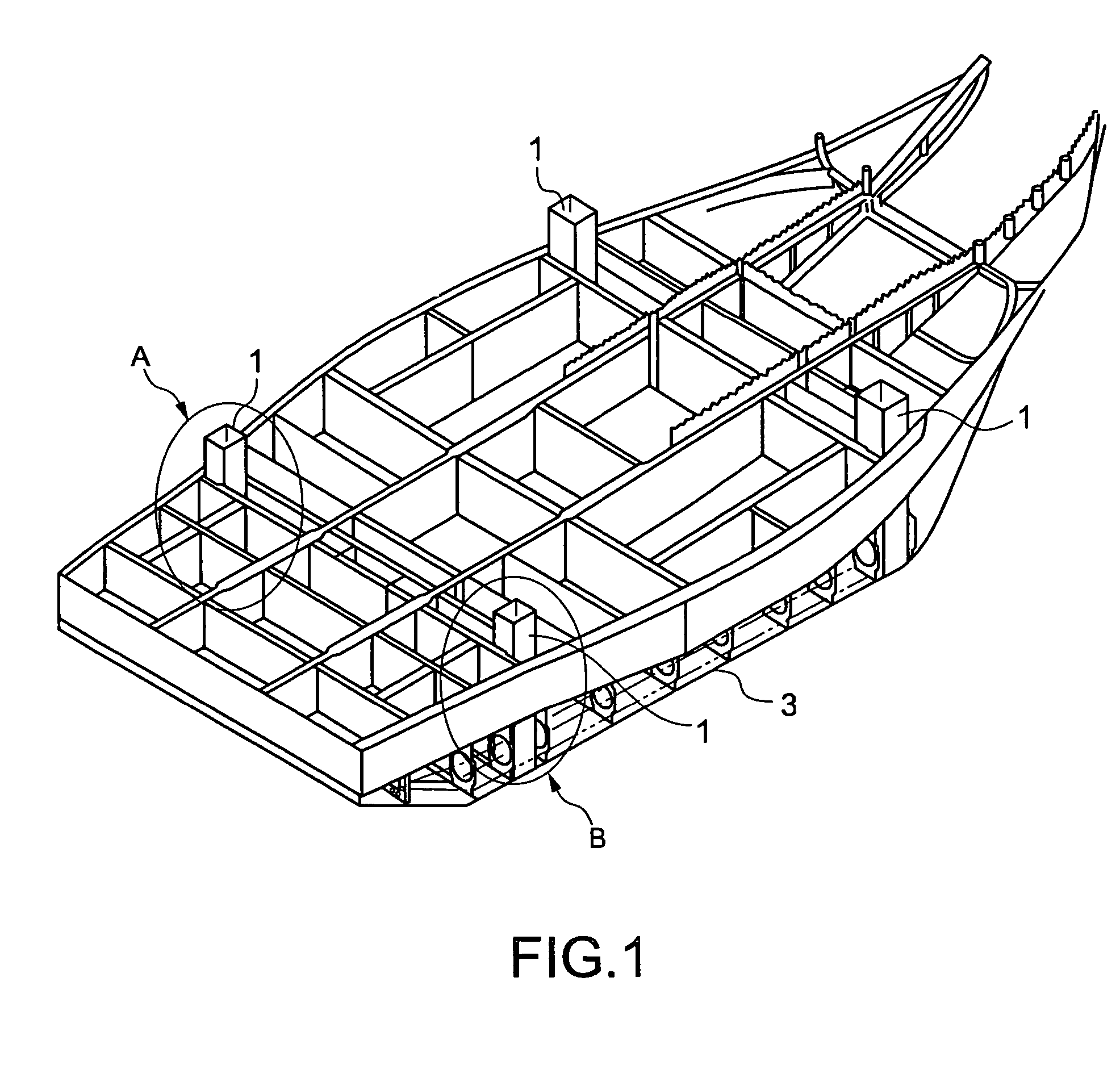
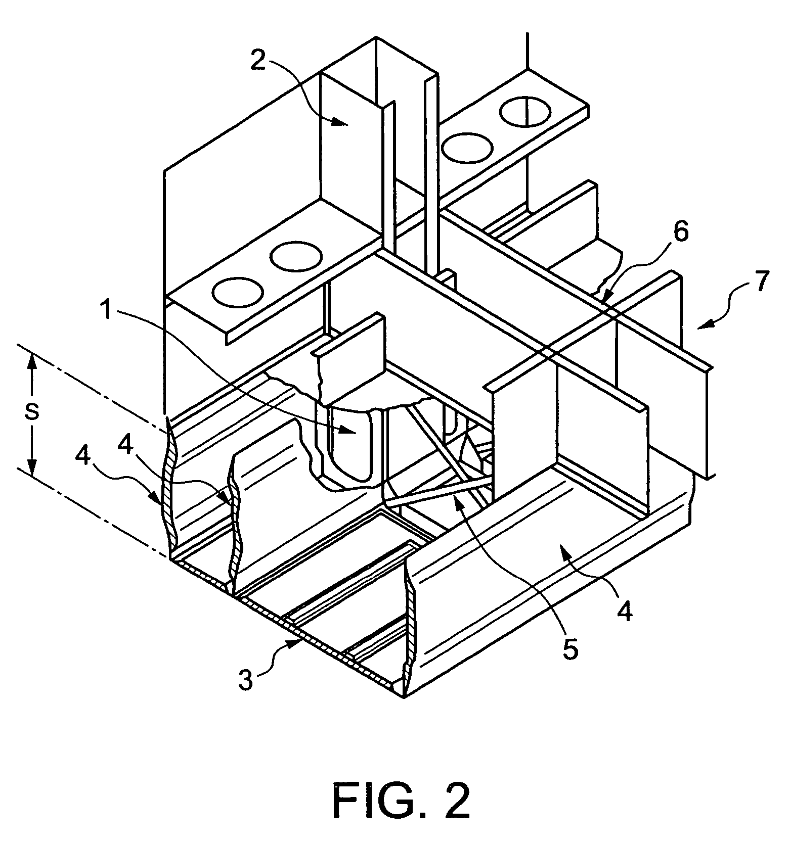
[0052]Firstly, the impact resistant structure of a helicopter will be explained by referring to FIGS. 1 to 3. The gray parts shown in FIG. 1 are energy absorbers 1 in bundled-tubes state. The energy absorbers 1 are arranged under the floor in accordance with the ground reaction force distribution at the time of crash situation on the general ground surface shown in FIG. 17 and are directly connected to a frame 2 as shown in FIGS. 2 and 3.

[0053]The energy absorbers 1 in the bundled-tubes state may be directly connected to the frame 2 almost directly under the side wall of the frame 2 where the impact load is concentrated at the time of crash situation shown in FIG. 17. In FIG. 1, numeral 3 indicates an under-floor outer skin or web and on th...


PUM

PropertyMeasurementUnit
speedaaaaaaaaaa
impact resistantaaaaaaaaaa
thicknessaaaaaaaaaa

Abstract

An impact resistant structure of a helicopter having an energy absorber positioned under a floor of the helicopter and directly connected to a cabin frame of the helicopter. The energy absorber is arranged in accordance with a distribution of a ground reaction force on a general ground at a time of crash situation. The energy absorber also includes a plurality of independent hollow tubes of fiber reinforced composite material integrally formed by bundling only the hollow tubes. The hollow tubes are arranged so as to reduce a number of intersecting wall surfaces of the hollow tubes.

Description

BACKGROUND OF THE INVENTION[0001]1. Field of the Invention[0002]The present invention relates to an impact resistant structure for a helicopter and an energy absorber used for the same.[0003]2. Description of the Related Art[0004]A helicopter is often operated in visual flight rule, or between mountains, or at a low altitude, because of its operating characteristics. Then, there is always a risk of accident due to contact with an obstacle. Therefore, an impact resistance is strongly required in a helicopter in order to keep survivability of crew members in the crash situations.[0005]The basic principle for the impact resistant structure of a helicopter is to adopt a continuous strong keel K for a nose H easily crushed and a bottom G easily crushed which are shown in FIG. 16(a) to prevent a floor D from structural failure on crash landing as shown in FIG. 16(b), to adopt a strong outer skin P as shown in FIG. 16(c), to adopt a strong beam B on the keel K, and to adopt a continuous st...

Claims


Application Information

Patent Timeline
Patent Type & Authority Patents(United States)
IPC IPC(8): F16F7/12B64C1/00B64C1/06B64C1/18B64C27/00B64C27/04
CPCB64C1/062F16F7/121F16F7/124F16F2224/0241B64C27/04
Inventor HAYASHI, TOHRU
Owner KAWASAKI HEAVY IND LTD
Why Eureka
Try Eureka