Ultrasound transducer assembly

a transducer and ultrasonic technology, applied in the field of ultrasonic imaging, can solve the problems of unwanted ringing in the transducer assembly, the known electronics carrier materials which satisfy the requirements of the electronics body are not suitable backing materials, and the difficulty in finding a carrier/backing material, so as to prevent damage to the components

Inactive Publication Date: 2005-11-08
VOLCANO CORP
View PDF80 Cites 35 Cited by
  • Summary
  • Abstract
  • Description
  • Claims
  • Application Information

AI Technical Summary

Benefits of technology

[0011]It is a further object to provide enhanced sensitivity to reflected signals from the walls of a cavity in order to provide improved image resolution.
[0012]It is a further object of the invention to meet the other objectives and maintain or reduce ringing and other sources of noise in a signal transmitted or received by the transducer assembly and to thereby provide a clearer image of a cavity.
[0013]It is yet another object of the present invention to provide a means for more easily fabricating the very small transducer elements of the transducer assembly of an ultrasound catheter.
[0019]The backing material for the transducer assembly is specifically selected for its characteristic low acoustic impedance and high absorption. The low acoustic impedance backing material absorbs signals coupled into the backing material and reduces the presence of ringing in the transducer assembly. In addition, a set of transducer electrodes are directly bonded to the transducer material thereby eliminating a capacitive glue layer previously associated with the transducer circuits.
[0021]The unique, multi-sectioned, structure of the probe assembly enables the designer of the probe assembly to separately select a material exhibiting the preferred structural and acoustic characteristic for the carrier of the integrated circuit components and the backing material for the transducer elements.
[0022]In order to prevent damage to the components of both the transducer assembly and the electronics body, these two portions of the ultrasound catheter probe assembly are separately manufactured and linked during the final stages of fabrication of the ultrasonic catheter.

Problems solved by technology

A drawback to the known ultrasound catheters is the difficulty in finding a carrier / backing material which provides the physical and acoustic qualities desired for advantageous use as the carrier for the electronics and the backing material for a transducer assembly comprising a highly sensitive transducer material.
However, the known electronics carrier materials which satisfy the requirements for the electronics body are not suitable backing materials for the presently preferred transducer assemblies comprising highly sensitive lead zirconate titanate (PZT) composites.
When the new, more sensitive PZT composites are used with the known electronic carrier material as the backing material for the transducer, unwanted ringing occurs in the transducer assembly when an acoustic signal is received or transmitted by the catheter.
The signal produced by the ringing reduces the quality of the signal transmitted by the transducer assembly and limits the foreseeable advantages of utilizing the more sensitive transducer materials in ultrasonic catheters.
The decreased signal quality attributed to the ringing limits the image quality provided by an ultrasound catheter.
The limited image quality restricts the usefulness of the ultrasound catheter for clinical and diagnostic imaging.

Method used


Image

  • Ultrasound transducer assembly
  • Ultrasound transducer assembly
  • Ultrasound transducer assembly

Examples


Embodiment Construction

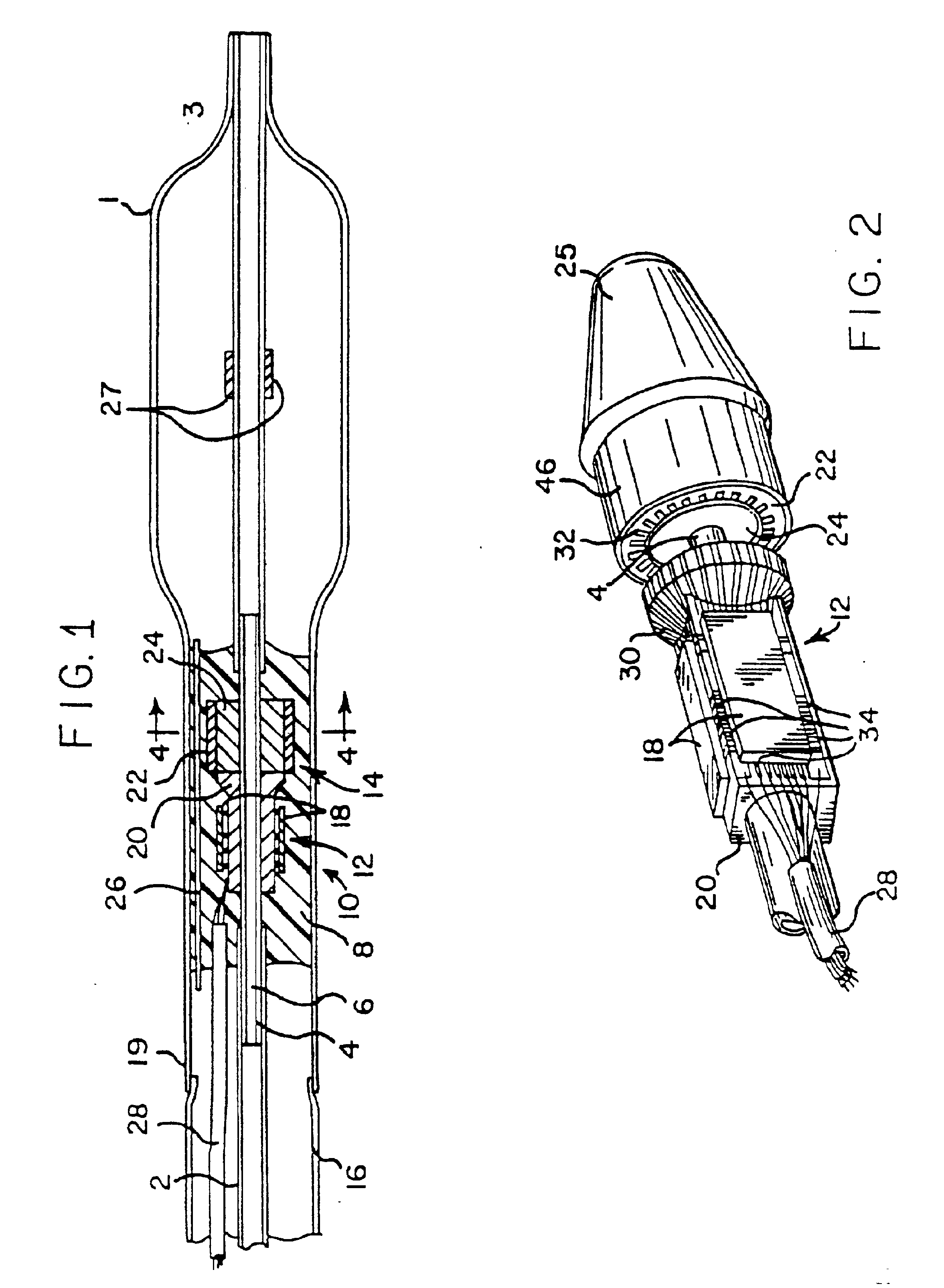
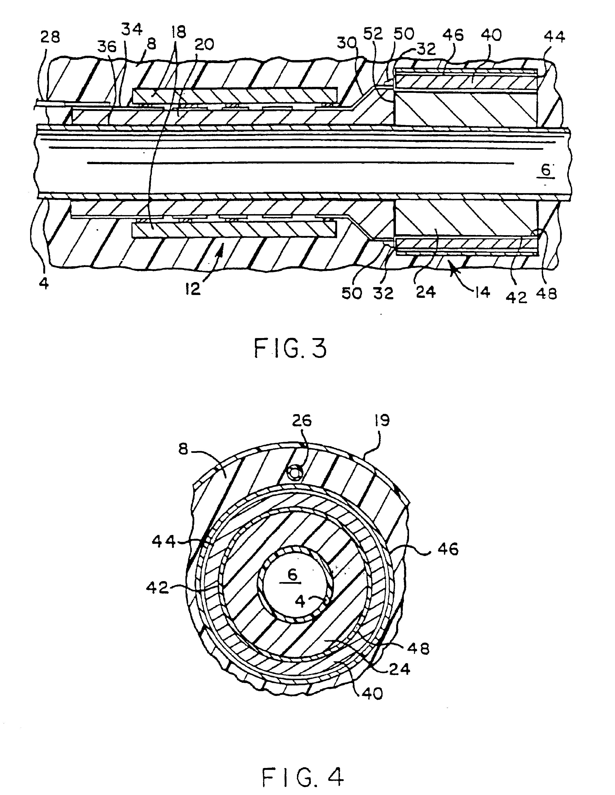
[0034]Though the present invention concerns the structure of the carrier / backing material for the electronics body and transducer assembly and changes to the physical layers of the transducer assembly, the invention is intended to be incorporated in general into an ultrasound catheter imaging system of the type described in Proudian, deceased et al. U.S. Pat. No. 4,917,097 the teachings of which are incorporated herein by reference. Furthermore, the present ultrasound catheter may be used to obtain images using a number of different imaging techniques including, for example, the imaging technique described in O'Donnell et al. U.S. Pat. No. 5,453,575, the teachings of which are expressly incorporated herein by reference.

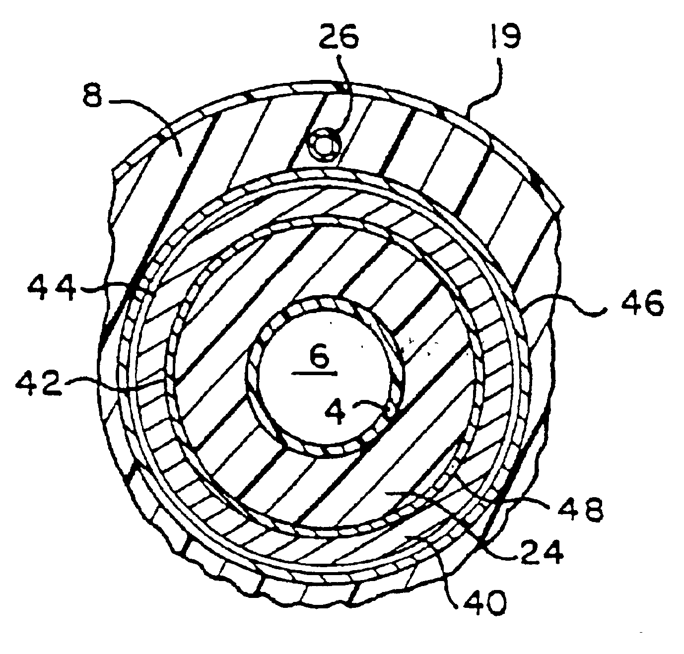
[0035]A cross-sectional view of a catheter embodying the present invention-is illustratively depicted in FIG. 1. The catheter shown in FIG. 1 carrying a balloon 1 is of the type which is generally used for angioplasty; however, the invention can be used in conjunction...


PUM

PropertyMeasurementUnit
outer diameteraaaaaaaaaa
temperaturesaaaaaaaaaa
circumferenceaaaaaaaaaa

Abstract

An ultrasound catheter is disclosed for providing substantially real-time images of small cavities. The ultrasound catheter is characterized by separate and distinct materials for backing the transducers and for carrying the electronics components. The separate materials comprise an electronics carrier meeting the requirements for holding the integrated circuitry of the ultrasound device and a backing material displaying superior characteristics relating to reducing ringing and minimizing the effect of other sources of signal degradation in the transducer assembly. Also, in accordance with the present invention, a technique is described for connecting the conductor lines of the separate transducer assembly and electronics body.

Description

[0001]This application is a continuation of Ser. No. 09 / 658,323, filed Sep. 8, 2000, now Pat. No. 6,283,920, which is a continuation of Ser. No. 09 / 324,692, filed Jun. 2, 1999, now Pat. No. 6,123,673 which is a continuation of Ser. No. 08 / 935,930, filed Sep. 23, 1997, now Pat. No. 5,938,615; which is a division of Ser. No. 08 / 712,166, filed Sep. 11, 1996, now Pat. No. 5,779,644; which is a continuation of Ser. No. 08 / 516,538, filed Aug. 18, 1995, now Pat. No. 5,603,327; which is a continuation of Ser. No. 08 / 234,848, filed Apr. 28, 1994, now Pat. No. 5,453,575; which is a continuation-in-part of Ser. No. 08 / 012,251, filed Feb. 1, 1993, now Pat. No. 5,368,037.INCORPORATION BY REFERENCE[0002]The applicants hereby incorporate by reference the description of an “Apparatus and Method for Imaging Small Cavities” described in Proudian et al. U.S. Pat. No. 4,917,097, the description of a “Dilating and Imaging Apparatus” described in Eberle et al. U.S. Pat. No. 5,167,233, and the description...

Claims


Application Information

Patent Timeline
Patent Type & Authority Patents(United States)
IPC IPC(8): A61B8/12G10K11/00A61B8/06A61B8/14B06B1/02B06B1/06G01S15/89
CPCA61B8/06A61B8/4483A61B8/4488B06B1/0633B06B1/067B06B1/0674G01S15/892G01S15/8979G01S15/899G10K11/004G10K11/008A61B8/12Y10T29/42A61B8/445B06B2201/76G01S15/8981A61B8/4494
Inventor EBERLE, MICHAEL J.RIZZUTI, GARY P.KIEPEN, HORST F.
Owner VOLCANO CORP
Why Eureka
Try Eureka