Transparent film
a technology of optical film and transparent film, applied in the field of transparent optical film, can solve the problems of significant deterioration of contrast, small electronic devices, and small size of electronic devices
- Summary
- Abstract
- Description
- Claims
- Application Information
AI Technical Summary
Benefits of technology
Problems solved by technology
Method used
Image
Examples
examples
[0247]Examples and Comparative Examples will be described below. Initially, methods for measuring each physical property value shown in Examples and Comparative Examples will be described.
[0248]
[0249]Glass transition temperature was measured in accordance with JIS K7121 using a differential scanning calorimeter (DSC) manufactured by. Seiko Instruments & Electronics Ltd. Specifically, 10 mg of a sample was placed in the DSC device and the sample was heated at a rate of 10° C. / min from room temperature, thereby measuring the glass transition temperature of the sample.
[0250]
[0251]Light transmission was measured using light of 550 nm in accordance with a method described in JIS K7105-1981 (5. 5).
[0252]
[0253]Haze was measured in accordance with a method described in JIS K7105-1981 (6. 4).
[0254]
[0255]A retardation was measured using light having a wavelength of 514.5 nm, using a polarization microspectrophotometer (TFM-120AFT manufactured by ORC Manufacturing Co., Ltd.).
[0256]
[0257]The an...
example 1a
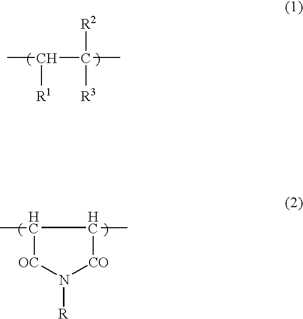
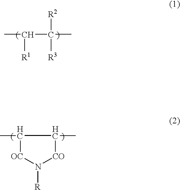
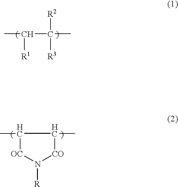
[0273]100 parts by weight (90% by weight) of an alternating copolymer consisting of isobutene and N-methyl maleimide (containing 50% by mole of N-methyl maleimide, the glass transition temperature was 157° C.) and 11 parts (10% by weight) of a thermoplastic copolymer consisting of styrene and acrylonitrile (containing 76% by weight of styrene and 24% by weight of acrylonitrile) were dissolved in methylene chloride, thereby obtaining a solution having a solid concentration of 15% by weight. The solution was flow-expanded on a biaxially stretched polyethylene terephthalate film laid on a glass plate. The resultant sample was left for 60 minutes at room temperature. Thereafter, the sample was peeled off the polyethylene terephthalate film, and the four sides of the sample were fixed and the film was dried for 10 minutes at 100° C. followed by drying for 10 minutes at 140° C. An unstretched film having a thickness of about 100 μm was obtained. This unstretched film had a retardation val...
example 1b
[0274]A sample film of 30 cm×10 cm was cut off the unstretched film obtained in Example 1a. The sample film was subjected to free end lengthwise uniaxial stretching in the length direction using a stretching test device (X4HD-HT manufactured by Toyo Seiki Seisaku-sho, Ltd.) under the conditions where the stretching rate was 10 cm / min, the stretch ratio was 1.5, and the stretching temperature was 140° C. A retardation film having a retardation of 143 nm was thus obtained (where the measurement wavelength was 550 nm). Re(400) / Re(550) was calculated to evaluate the wavelength dependence of the retardation film. As a result, Re(400) / Re(550) was 1.09. Further, the photoelasticity of the retardation film was 6×10⁻¹³ cm2 / dyn.
PUM
| Property | Measurement | Unit |
|---|---|---|
| haze | aaaaa | aaaaa |
| surface energy | aaaaa | aaaaa |
| thickness | aaaaa | aaaaa |
Abstract
Description
Claims
Application Information
 - R&D
- Intellectual Property
- Life Sciences
- Materials
- Tech Scout
- Unparalleled Data Quality
- Higher Quality Content
- 60% Fewer Hallucinations
Browse by: Latest US Patents, China's latest patents, Technical Efficacy Thesaurus, Application Domain, Technology Topic, Popular Technical Reports.
© 2025 PatSnap. All rights reserved.Legal|Privacy policy|Modern Slavery Act Transparency Statement|Sitemap|About US| Contact US: help@patsnap.com


