DC-DC converter with reduced electromagnetic interference

a technology of electromagnetic interference and converter, applied in the field of dc-dc converter, can solve the problems of imposing more restrictive limitations, interfering with other electronic devices such as computers or televisions, and communication may interfere with other electronic devices, so as to achieve the effect of reducing spurious emissions

Inactive Publication Date: 2005-11-29
QORVO US INC
View PDF38 Cites 182 Cited by
  • Summary
  • Abstract
  • Description
  • Claims
  • Application Information

AI Technical Summary

Benefits of technology

[0007]The present invention minimizes spurious emissions by spreading the frequency at which an oscillator in a switching power supply operates. Specifically, the present invention represents a modification to a switching power supply that can be used in a myriad of mobile terminals, although it is especially well suited for use with Global System for Mobile Communications (GSM) compatible mobile terminals.
[0013]In a third embodiment, a single DAC and a single capacitor are used with current mirrors to reflect the current into the current source and current sink. This embodiment uses more current than the first embodiment, but has the advantage of taking up less space.

Problems solved by technology

An unfortunate side effect of the convenience of this wireless communication is that the signal-carrying electromagnetic radiation that forms the backbone of the communication may interfere with other electronic devices.
While interfering with other electronic devices like a computer or television is problematic, it is also possible for multiple mobile terminals operating in proximity to one another to have cross channel EMI.
On top of the FCC emissions rules, the various communication protocols used by mobile terminals may impose more restrictive limitations with specific attention paid to side band transmission levels.
If the DC-DC converter is used to provide a Vcc supply voltage to a saturated power amplifier, this ripple may mix with the radio frequency carrier to generate spurious side band signals.
This substitution avoids the ripple issues, but does so at the expense of decreased efficiency and shorter battery life.

Method used


Image

  • DC-DC converter with reduced electromagnetic interference
  • DC-DC converter with reduced electromagnetic interference
  • DC-DC converter with reduced electromagnetic interference

Examples


first embodiment

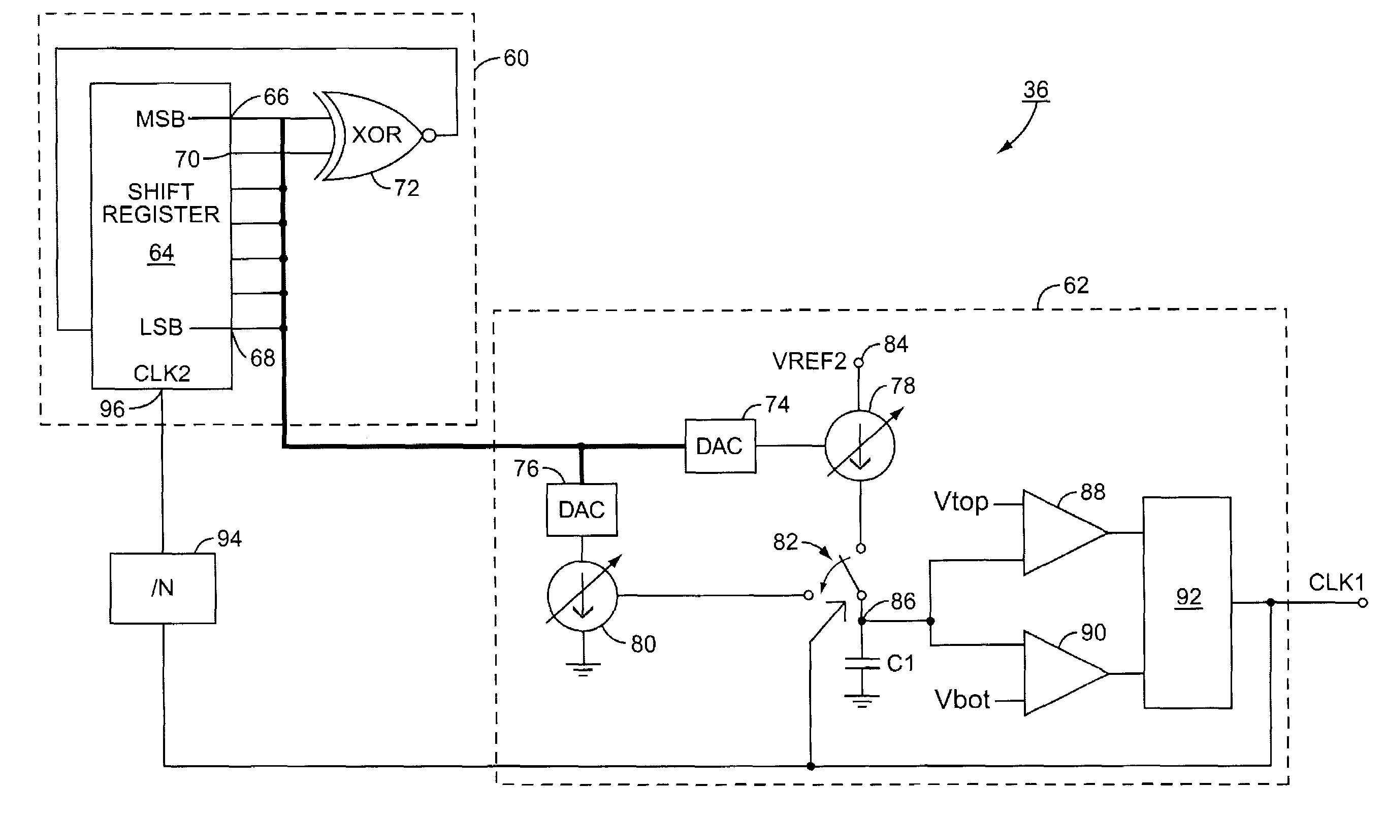
[0038]In a first embodiment, illustrated in FIG. 4, the oscillator 36 includes a pseudo random number generator 60 and a clock generation circuit 62. The pseudo random number generator 60 includes a seven bit shift register 64 with a most significant bit (MSB) output 66 and a least significant bit (LSB) output 68. Two outputs (which in the exemplary embodiment are the MSB output 66 and the next most significant bit output 70) are directed to an exclusive OR (XOR) gate 72. The output of the XOR gate 72 is fed back into an input of the shift register 64, thereby causing the shift register 64 to count in a pseudo random fashion and thus output a pseudo random number. This is known as a linear feedback shift register (LFSR) and is well known in the art. Other pseudo random number generators 60 could also be used if needed or desired. Likewise, the number of bits in the shift register may vary from embodiment to embodiment as needed or desired.

[0039]In addition to the outputs sent to the...

second embodiment

[0050]the clock generation circuit 62 is presented in FIG. 6. In this embodiment, the pseudo random number generator (PNG) 60 outputs the pseudo random number, which in turn controls switches 152, 154, 156. The switches 152, 154, 156 selectively activate capacitors C2, C3, and C4 respective to node 158. It should be appreciated that the pseudo random number output by the pseudo random number generator 60 maps which capacitors are activated. Also, there may be more or fewer capacitors than C2–C4. For example, if the pseudo random number generator 60 used a seven bit register, there might be seven capacitors, with each bit mapping to a capacitor. As another alternative, a varactor could be used in place of a plurality of capacitors, and the amount of capacitance would be set by the pseudo random number.

[0051]In this context, the capacitors C2, C3, and C4 may be physically connected to the node regardless of the position of the switches 152, 154, 156, but the capacitors C2, C3, and C4 ...

third embodiment

[0057]A third embodiment is illustrated in FIG. 8. The PNG 60 outputs a pseudo random number to a DAC 250 that in turn controls a variable current source 252. The variable current source 252 outputs a current that is mirrored from a first Field Effect Transistor (FET) 254 to a second FET 256 and a third FET 258. The current mirrored into the second FET 256 forces a current to exist in a fourth FET 260. The current in the fourth FET 260 is mirrored into a fifth FET 262. While FETs are illustrated, other current mirroring mechanisms could also be used.

[0058]The third FET 258 acts as a current sink and the fifth FET 262 acts as a current source for the capacitor C1 depending on the position of the switch 264. This embodiment has the advantage of taking up less space in a semiconductor than the two DAC arrangement of FIG. 4, but at the expense of wasted current.

[0059]The comparators 88, 90 measure the voltage at node 266 and set and reset the flip-flop 92 much as previously described. T...


PUM


Abstract

A DC-DC converter includes a variable frequency oscillator, a control system and a power train. The DC-DC converter is well suited for use in a cell phone. The control system uses the output of the oscillator to control the power train. The oscillator varies its frequency as a function of a pseudo random number generator, thereby reducing electromagnetic interference caused by ripple in the output of the DC-DC converter.

Description

FIELD OF THE INVENTION[0001]The present invention is related to a DC-DC converter and specifically a switching regulator DC-DC converter with an oscillator whose frequency changes to reduce electromagnetic interference.BACKGROUND OF THE INVENTION[0002]Mobile terminals such as cellular phones have become ubiquitous in modern society. Mobile terminals rely on sending an electromagnetic signal through the air to a base station and receiving electromagnetic signals through the air from the base station. An unfortunate side effect of the convenience of this wireless communication is that the signal-carrying electromagnetic radiation that forms the backbone of the communication may interfere with other electronic devices. This phenomenon is known variously as electromagnetic interference (EMI) or electromagnetic compatibility (EMC).[0003]While interfering with other electronic devices like a computer or television is problematic, it is also possible for multiple mobile terminals operating...

Claims


Application Information

Patent Timeline
Patent Type & Authority Patents(United States)
IPC IPC(8): H02M3/156H03K7/08H03K7/10H04B15/02H04B15/04
CPCH02M3/156H03K7/08H03K7/10H04B15/02H04B15/04H02M1/44H04B2215/067
Inventor DENING, DAVID
Owner QORVO US INC
Why Eureka
Try Eureka