Valve timing adjusting device

Active Publication Date: 2005-12-06
MITSUBISHI ELECTRIC CORP
View PDF7 Cites 10 Cited by
  • Summary
  • Abstract
  • Description
  • Claims
  • Application Information

AI Technical Summary

Benefits of technology

[0016]Accordingly, according to the present invention arranged thus above, the invention provides the internal surface of the engaging hole and the surrounding area of the engaging hole with satisfactory mechanical strength or surface hardness enough for resisting deformation of the engaging hole or wear-out of the edge of the engaging hole caused by putting in and out of the r

Problems solved by technology

On this account, an alternating load (reaction force) of the camshaft causes the peripheral surface of the lock pin to repeatedly abut against the inner surface of the engaging hole, which may enlarge an internal diameter of the engaging hole when the engaging hole has poor mechanical strength.
Moreover, when the lock pin re

Method used


Image

  • Valve timing adjusting device
  • Valve timing adjusting device
  • Valve timing adjusting device

Examples


Example

First Embodiment

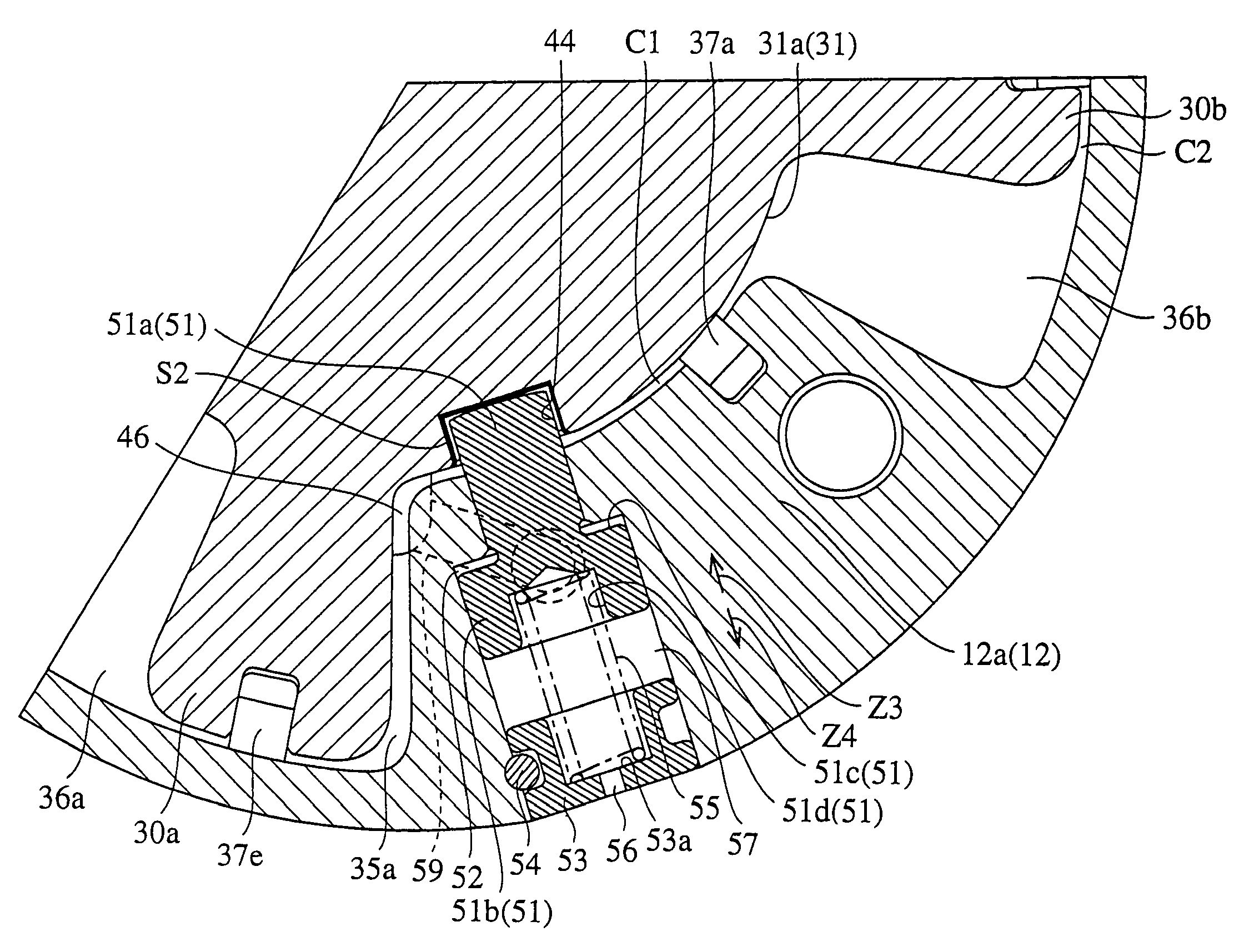
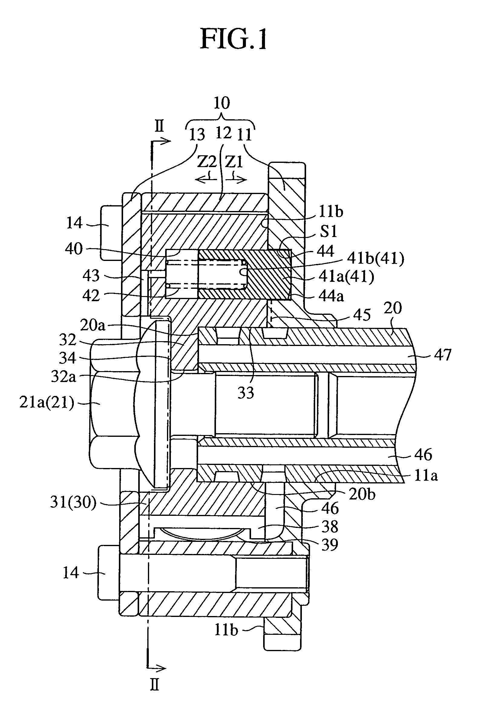
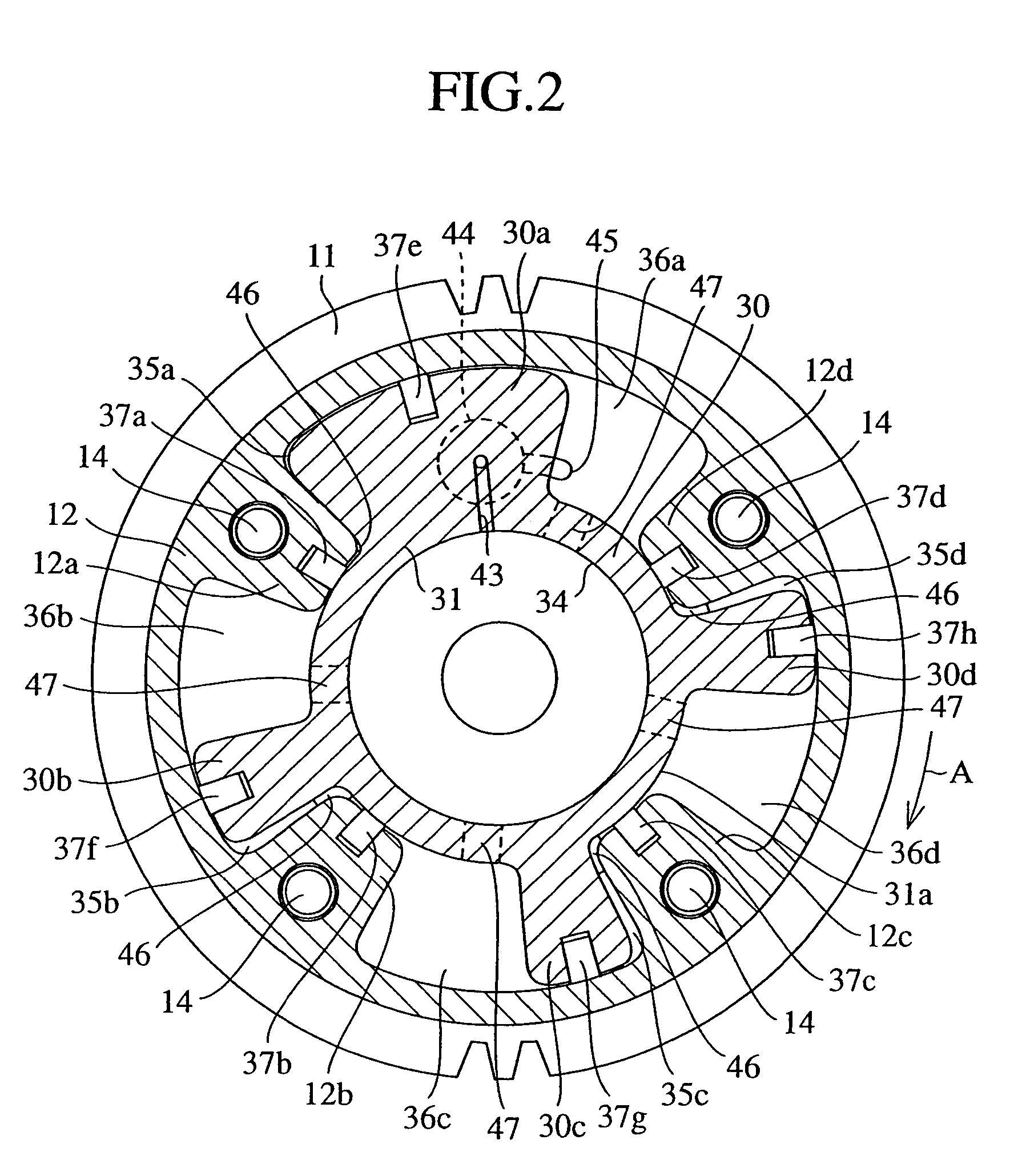
[0025]FIG. 1 is an axial sectional view showing an internal structure of a valve timing adjusting device according to the first embodiment of the present invention; FIG. 2 is a radial sectional view taken along line II—II in FIG. 1; and FIG. 3 is an axial sectional view showing a sprocket of the valve timing adjusting device shown in FIG. 1.

[0026]A valve timing adjusting device 1 is generally composed of a first rotor 10 connected with a crank shaft (not shown) of an engine (not shown) by a power transmitting member (not shown) such as a chain and rotating synchronously with the crank shaft, and a second rotor 30 integrally fixed on an end face of a camshaft 20 of an intake side or an exhaust side camshaft (hereinafter referred to as a camshaft) by a bolt 21 and provided relatively rotatably within the first rotor 10 by a predetermined angle relative to the first rotor. The valve timing adjusting device 1 has, as will be described later, a structure of so-called axia...

Example

Second Embodiment

[0048]FIG. 4 is a radial sectional view showing an internal structure of a valve timing adjusting device according to the second embodiment of the present invention; FIG. 5 is an axial sectional view taken along line V—V in FIG. 4; FIG. 6 is an enlarged radial sectional view showing an engaging hole shown in FIG. 4 and a rotation regulating member engaging into the engaging hole; and FIG. 7 is an enlarged radial sectional view showing the engaging hole shown in FIG. 4 and the rotation regulating member disengaged from the engaging hole. In the second embodiment, the same components commonly used in the first embodiment are designated by the same reference numerals, and therefore explanation thereof is omitted for brevity's sake.

[0049]Despite of a valve timing adjusting device that is the most lagged position lock type device as with the first embodiment, the feature of the second embodiment is in that the second embodiment having a so-called radial lock structure, i...

Example

Third Embodiment

[0062]The feature of the third embodiment is in that an oxide film forming process is adopted as surface treatment to an internal surface of the engaging hole and a surrounding area of opening of the engaging hole (region) in the first embodiment or the second embodiment. That is, applying the oxide film forming process such as the “Alumite” (registered trademark) process to the internal surface and the surrounding area of opening of the engaging hole formed in either of the first rotor and the second rotor provides the region with satisfactory mechanical strength or surface hardness enough for resisting deformation of the engaging hole and wear-out of an edge of opening of the engaging hole caused by putting in and out of the rotation regulating member.

[0063]Here, the Alumite (registered trademark) process is a well-known surface treatment technology dedicated to anodization of aluminum to form a corrosive oxide film thereover when the member in which the engaging h...


PUM

PropertyMeasurementUnit
Mechanical strengthaaaaaaaaaa
Hardnessaaaaaaaaaa

Abstract

A region including an engaging hole is given surface treatment such as partial quench hardening by induction hardening for improving surface hardness of the region. The partial quench hardening by induction hardening provides the region with satisfactory mechanical strength or surface hardness enough for resisting deformation of the engaging hole and wear-out of an edge of opening of the engaging hole caused by putting in and out of the lock pin.

Description

BACKGROUND OF THE INVENTION[0001]1. Field of the Invention[0002]The present invention relates to a valve timing adjusting device adjusting opening and closing timing of an intake valve and / or exhaust valve of an internal combustion engine such as an engine (hereinafter referred to as an “engine”).[0003]2. Description of the Related Art[0004]Conventionally, a valve timing adjusting device is generally composed of a first rotor connected to a crank shaft as an output shaft of an engine with a power transmitting member such as a chain, and rotating synchronously with the crank shaft, and a second rotor integrally secured on an end face of an intake side camshaft or an exhaust side camshaft, and provided relatively rotatably by only a predetermined angle within the first rotor.[0005]The first rotor is made by integrating a sprocket having a bearing integrally rotating with the camshaft being subjected to rotational driving force of the crankshaft, and slidingly contacting a peripheral s...

Claims


Application Information

Patent Timeline
IPC IPC(8): F01L1/34F01L1/344
CPCF01L1/022F01L1/3442F01L2101/00F01L2103/00F01L2301/00F01L2303/00
Inventor KINUGAWA, HIROYUKIYAMAUCHI, MAKOTO
Owner MITSUBISHI ELECTRIC CORP
Why Eureka
Try Eureka