Method and device for detecting a phase of a four-stroke gasoline engine

a four-stroke gasoline engine and detection method technology, applied in the direction of machines/engines, electrical control, mechanical apparatus, etc., can solve the problems of unburnt air/fuel mixture never being pushed into the catalytic converter, system cost increase, and difficult adjustment, etc., to achieve reliable cost-effective phase detection

Inactive Publication Date: 2005-12-06
ROBERT BOSCH GMBH
View PDF10 Cites 4 Cited by
  • Summary
  • Abstract
  • Description
  • Claims
  • Application Information

AI Technical Summary

Benefits of technology

[0009]A method and device according to an example embodiment of the present invention may have an advantage over the related art due to the facts that they may be achieved relatively inexpensively, they may make precise detection of the phase possible, and, in particular, they may also be used in a gasoline direct injection engine. Following phase detection, the engine may advantageously be started via correct injection and ignition according to the phase with the crankshaft already rotating.
[0010]Thus, according to the present invention and in contrast to the above-mentioned twin ignition systems, the engine is turned using ignition and without using injection. In contrast to German Patent Application No. DE 198 17 447, adequately high ignition power is supplied, resulting in an ignition at each crankshaft rotation without having to set a precise threshold value.
[0018]The measuring device and the analyzing device used according to the present invention may be integrated. In particular, no additional interference occurs in the primary and secondary circuits during a measurement of the primary voltage induced at the primary winding, so that reliable cost-effective phase detection is possible without further interference in the ignition operation.

Problems solved by technology

Such systems require additional expensive means.
However, unburnt air / fuel mixture is never pushed into the catalytic converter in engines having multipoint injection.
However, such a twin ignition system including ignition and injection in each crankshaft revolution may not be used in a gasoline direct injection (GDI) engine since, in these engines, injection must take place precisely during the intake stroke or at the beginning of the compression stroke, and injection during the exhaust stroke is not permitted, since otherwise unburnt fuel may be pushed out into the catalytic converter.
The required threshold value of the ignition power for differentiating the top dead centers may turn out to be different, in particular in different engines, so that a precise adjustment is difficult.
Furthermore, analysis of the ion current measured for a precise differentiation between I-TDC and CC-TDC is relatively complex.

Method used


Image

  • Method and device for detecting a phase of a four-stroke gasoline engine
  • Method and device for detecting a phase of a four-stroke gasoline engine
  • Method and device for detecting a phase of a four-stroke gasoline engine

Examples


Embodiment Construction

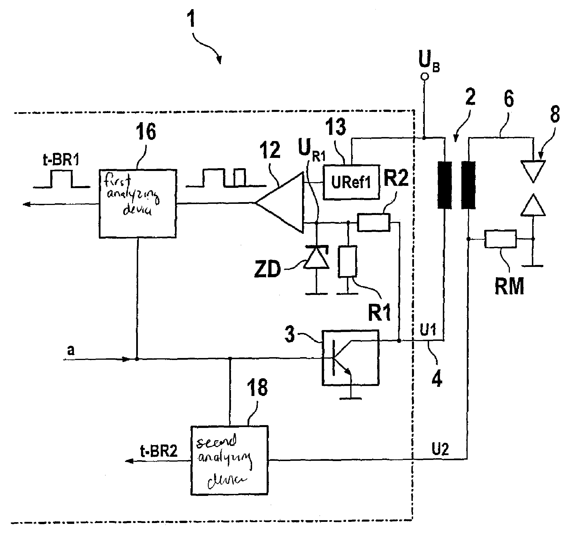
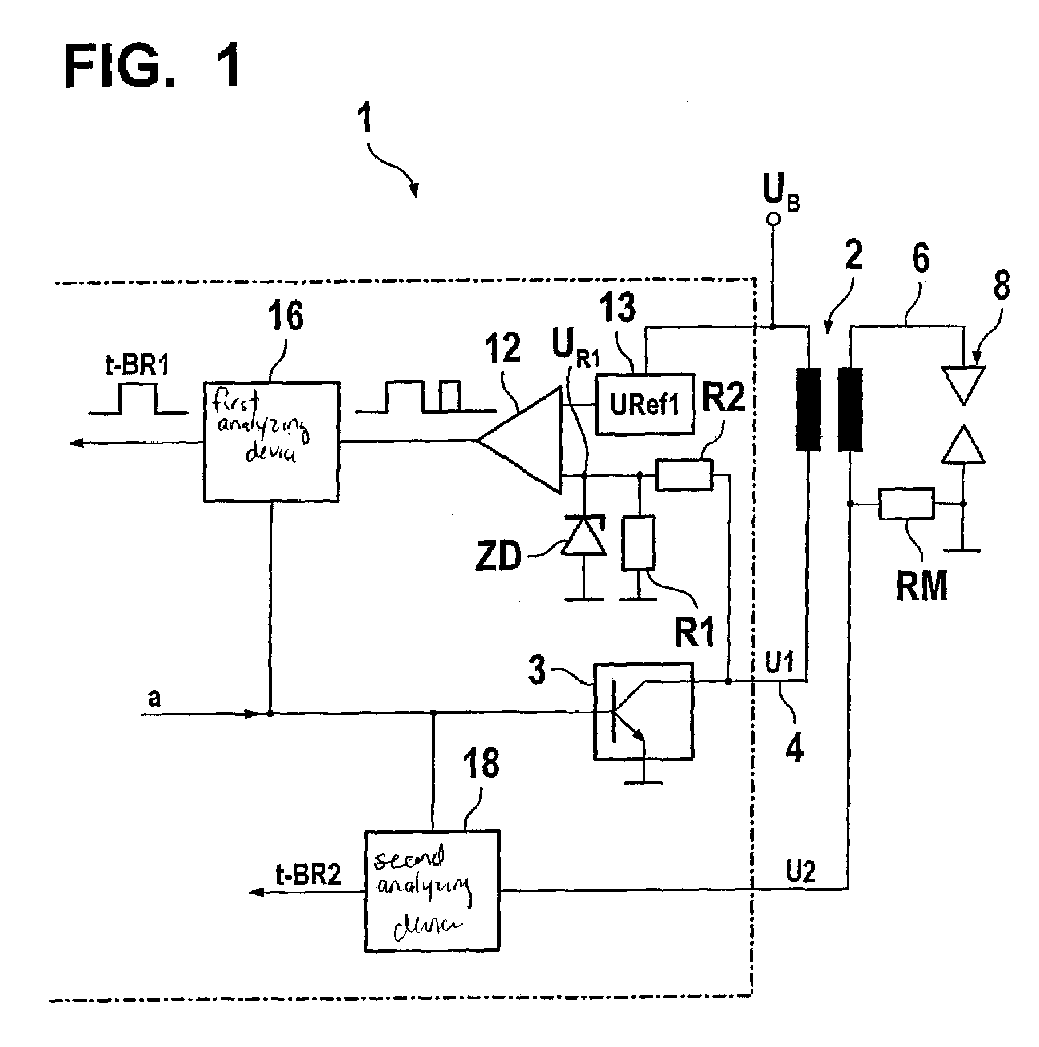
[0022]A primary winding of an ignition coil 2 and an ignition transistor 3 are situated in a primary circuit 4 between a battery connection of vehicle voltage UB and ground according to FIG. 1. Ignition transistor 3 is triggered by a control signal a and, in its low-resistance state, i.e., at high voltage level of control signal a, enables a primary current in primary circuit 4 via which a magnetic field is created in ignition coil 2. During subsequent blocking of ignition transistor 3 in its high-resistance state, i.e., at low voltage level of control signal a, the collapsing magnetic field of ignition coil 2 induces a voltage surge in its secondary winding, resulting in a spark discharge at a spark plug 8. At this juncture, according to the particular secondary current, a voltage U2 drops across shunt resistor RM, connected in series, vis-à-vis the grounded terminal of ignition coil 8.

[0023]According to an example embodiment of the present invention, the ignition system shown, inc...


PUM


Abstract

A method and a device for detecting the phase of a four-stroke gasoline engine, a gasoline direct injection engine in particular. For reliable phase detection involving relatively little expense during a starting phase, a crankshaft is turned together with at least one piston; ignition is triggered via an ignition coil in at least two successive top dead centers of the piston without a supply of fuel. A primary current or a secondary current, or a primary voltage or a secondary voltage are measured in a measuring period which extends at least over a spark duration after the ignition. From the comparison of the measuring signals of successive ignitions, a conclusion is drawn as to which of the successive top dead centers is an ignition top dead center and which is a charge cycle top dead center.

Description

FIELD OF THE INVENTION[0001]The present invention relates to a method and a device for detecting a phase of a four-stroke gasoline engine.BACKGROUND INFORMATION[0002]In engines whose fuel injectors are electronically controlled via an ECU (electronic control unit) it is necessary to determine the phase position at the start of the internal combustion engine. Since a combustion cycle extends over two 360° revolutions of the crankshaft, it is only determined via the phase position whether the piston is in the compression stroke or in the exhaust stroke during the upward motion.[0003]Different systems are known in this connection. An additional transducer wheel may be provided on the camshaft or coasting detection may be performed. Such systems require additional expensive means.[0004]Furthermore, in multipoint injection engines, the phase may be determined in what is known as a twin ignition system via fuel injection and ignition at the successive top dead centers.[0005]Each second ig...

Claims


Application Information

Patent Timeline
Patent Type & Authority Patents(United States)
IPC IPC(8): F02P3/04F02D41/34F02D45/00F02P17/12
CPCF02D41/009F02P17/12
Inventor OTT, KARLBINDER, HELMUT
Owner ROBERT BOSCH GMBH
Why Eureka
Try Eureka