Method of removing mercury from flue gases

a technology of flue gas and mercury, which is applied in the direction of cadmium sulfide, zinc sulfide, inorganic chemistry, etc., can solve the problems of additional and expensive operating measures

Inactive Publication Date: 2005-12-06
FISIA DEUT GMBH AND +1
View PDF14 Cites 35 Cited by
  • Summary
  • Abstract
  • Description
  • Claims
  • Application Information

AI Technical Summary

Benefits of technology

[0015]It can also be expedient to heat up or cool off the gas that exits the catalyzer to a temperature that is suitable for m

Problems solved by technology

For this purpose, the use of a sodium polysulfide and/or a potassium polysulfide and/or an ammonium polysulfide (see DE

Method used


Image

  • Method of removing mercury from flue gases
  • Method of removing mercury from flue gases
  • Method of removing mercury from flue gases

Examples


Embodiment Construction

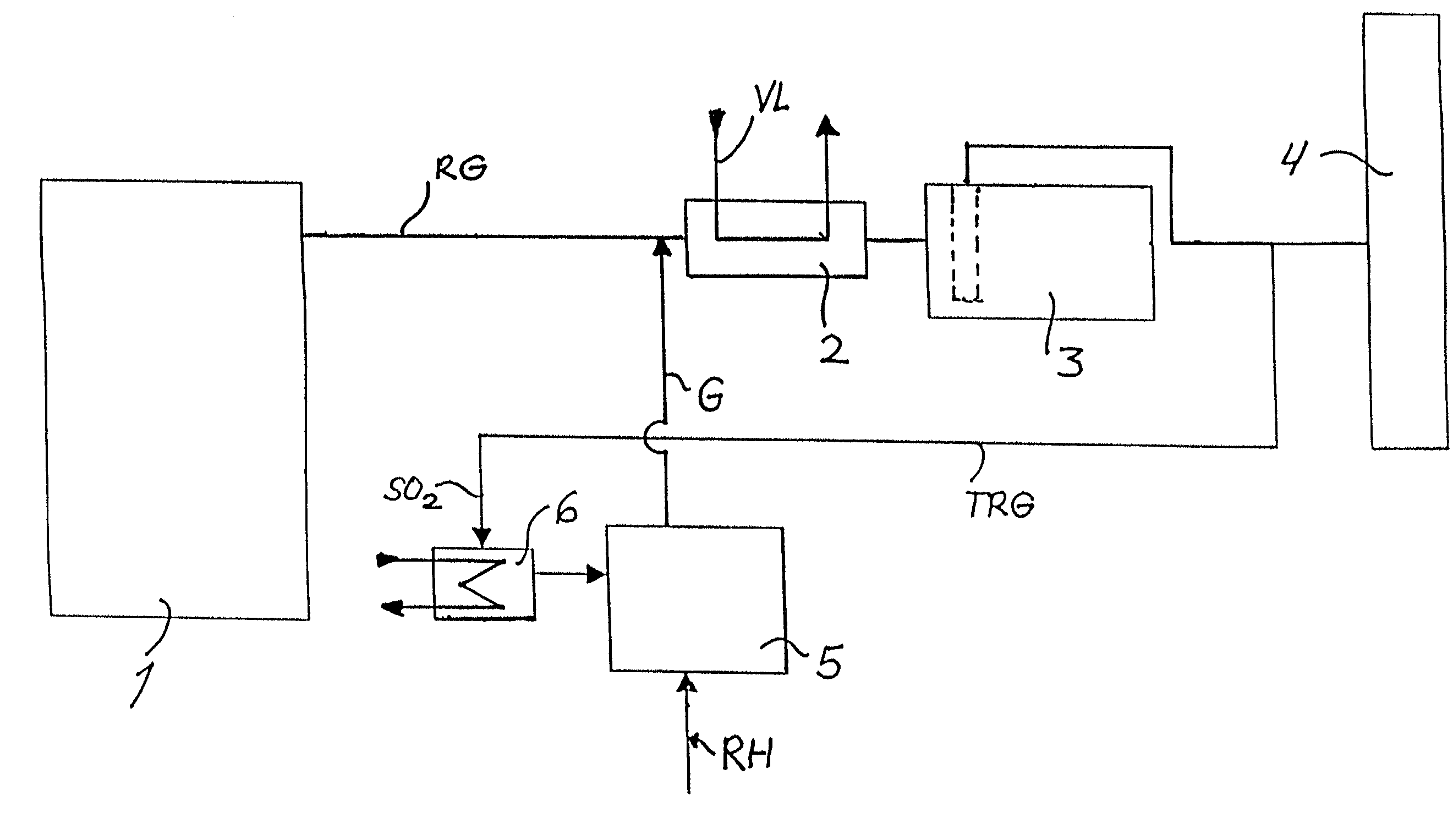
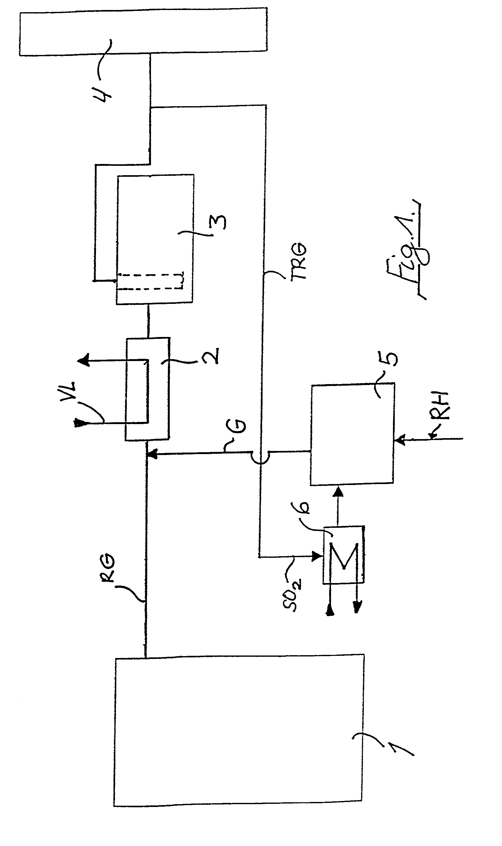
[0020]The flue gases RG exiting from a block or unit 1 representing a power plant are guided across an air preheater 2 that serves for preheating air for combustion VL. The gas is subsequently guided across a separator 3 in the form of a fibrous filter and is then discharged into the atmosphere via a chimney 4. For the sake of simplicity, other measures that might be undertaken for desulfurization and / or reduction of NOx levels are not illustrated in the drawing.

[0021]A catalyzer or catalytic converter 5 is provided for the provision of a gas G that contains H2S / S; this catalyzer is preferably a Co / Mo catalyzer from the company Akzo Nobel, of the Netherlands.

[0022]Supplied to the catalyzer 5, as a gas that contains SO2, is a partial stream TRG of the flue gas that is withdrawn downstream of the fibrous filter 3 and that is heated up in such a way in a gas / gas heat exchanger 6 disposed upstream of the catalyzer 5 that the temperature of, for example, 205° C. required for the catalysi...


PUM

PropertyMeasurementUnit
Temperatureaaaaaaaaaa
Metallic bondaaaaaaaaaa

Abstract

A method of removing metallic mercury and ionic mercury from flue gases, especially of a power plant, is provided. A gas that contains sulfur dioxide, or other adequate amounts of sulfur in the form of H2S or COS, and a gas that contains hydrogen, are conveyed to a catalyzer for producing a gas that contains elemental sulfur and hydrogen sulfide. This gas is conveyed to flue gas upstream of a separator, wherein mercury in the flue gas reacts with the sulfur and ionic sulfur in the gas and is separated out in the separator.

Description

BACKGROUND OF THE INVENTION[0001]The present invention relates to a method of removing metallic mercury (Hg0) and ionic mercury (Hg+2) from flue gases, especially of a power plant, whereby the mercury reacts with elemental sulfur (S0) and ionic sulfur (S−2) and is separated off in a separator.[0002]From EP 0 709 128 A2 it is known to remove metallic mercury and ionic mercury with the aid of elemental sulfur and hydrogen sulfite by introducing into the flue gas a sodium polysulfide, especially sodium tetrasulfide (Na2S4). This method is utilized in refuse incinerators.[0003]There is also a need for reducing the mercury concentration in the large flue gas streams of power plant flue gases. For this purpose, the use of a sodium polysulfide and / or a potassium polysulfide and / or an ammonium polysulfide (see DE 41 23 907 A1) is less suitable, since this represents an additional and expensive operating measure for the power plant.[0004]It is therefore an object of the present invention to ...

Claims


Application Information

Patent Timeline
IPC IPC(8): A62D3/00B01D53/64
CPCB01D53/64
Inventor HOLSTE, REINHARDFEY, WOLFGANG
Owner FISIA DEUT GMBH AND
Why Eureka
Try Eureka