
Power inverter with optical isolation

a technology of optical isolation and power inverter, applied in power conversion systems, instruments, electric digital data processing, etc., can solve problems such as limiting the application of multi-level converter systems and their application to distributed energy resource applications, and limiting the application of power conversion technologies

Inactive Publication Date: 2005-12-06
ALRAK INC
View PDF2 Cites 84 Cited by
  • Summary
  • Abstract
  • Description
  • Claims
  • Application Information

AI Technical Summary

Problems solved by technology

Several issues are impeding state-of-the-art, next-generation advances in power conversion technologies.
Among these issues are the problems associated with existing thyristor-based, multi-level converter systems and how they are applied to distributed energy resource (DER) applications.
The mature versions of these designs have severe limitations due to one or more of the following:Slow switching speeds requires larger sized reactive compensation components (a power density and cost problem).The reverse bias safe operating area (RBSOA) of many thyristor-based devices is considered small (a design constraint).The general requirement for expensive, anti-parallel diodes across the main switching devices, which cannot withstand high rates of current change (di / dt) (a failure mode, cost, and efficiency problem).The general requirement for shoot-through protection, often in the form of a series inductor along with a resistive-diode for current protection, as well as some form of a voltage clamp circuit to prevent the device from over voltage failure (over voltage / current as well as cost and efficiency problems).Difficulties exist in separating the gate drive control section from the high voltage / high current power stage (cost and isolation problems).The physical size of existing systems often prevents their wide-scale deployment in space critical applications, such as those on board ship, aircraft, or spacecraft (the power density problem).The requirement for external deionized (DI) water cooling systems to dissipate heat due to switching losses.
These systems have high life-cycle maintenance costs and reduce overall system reliability.

Method used


Image

  • Power inverter with optical isolation
  • Power inverter with optical isolation
  • Power inverter with optical isolation

Examples


Embodiment Construction

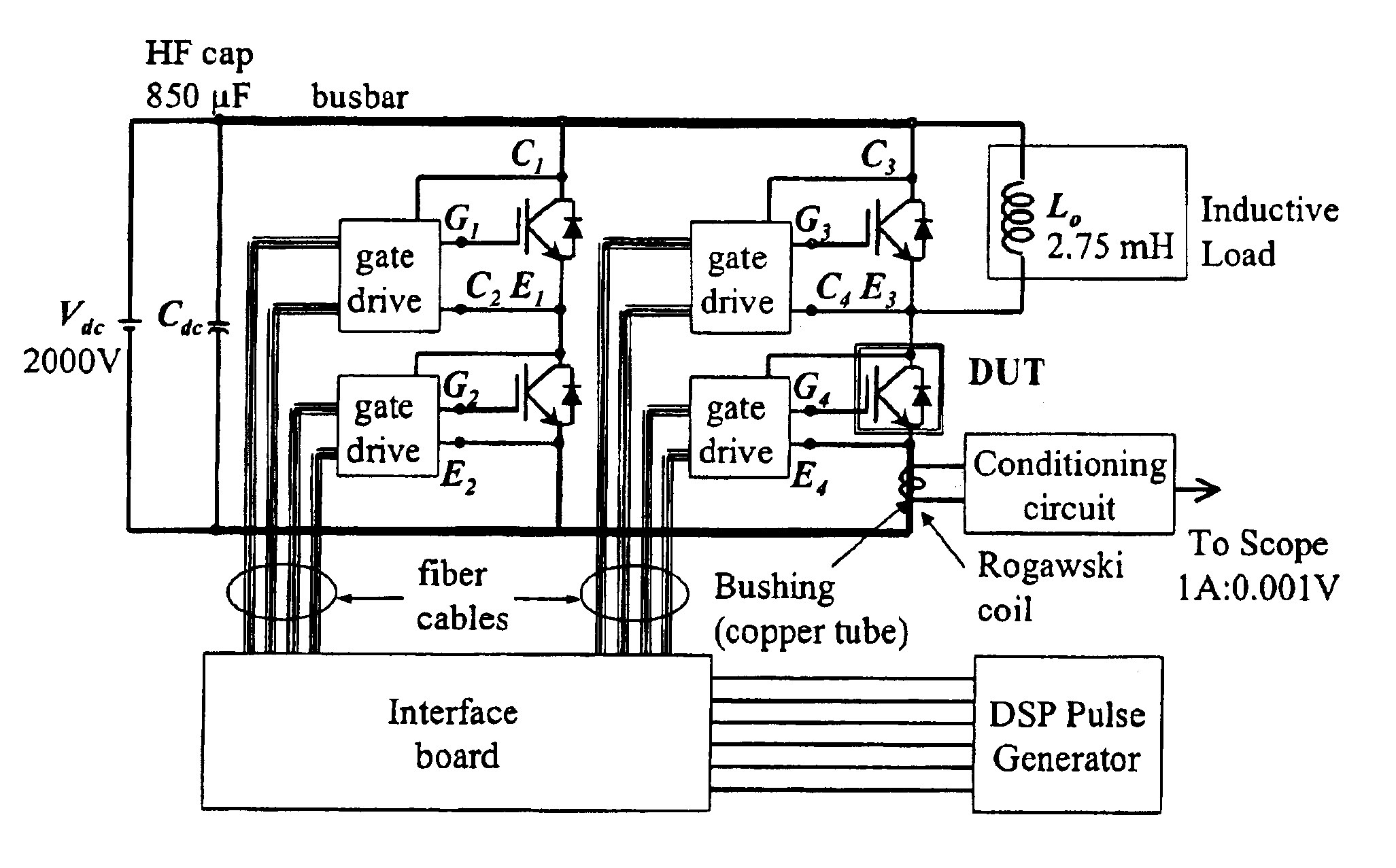
[0056]To combat the above-listed limitations of the related art, and to enable the creation of efficient, reliable, high-powered converters, a new generation of power stage technology is being developed. Specifically, these power stages are optically interconnected, are based upon the latest IGBT technologies, and use innovative self-contained cooling technologies to provide extremely compact and reliable systems. The advantages of implementing all-optical sensor and feedback schemes, when combined with all-optical gate drive control signals in high-power cascaded inverters are numerous: the high-power output stage can be completely isolated from the lower-potential input and control subsystem, resulting in higher reliability, reduced personnel hazard, and simplified gate control implementation.

[0057]The devices and methods described herebelow provide low-cost production-ready fiber optic field sensors capable of measuring tens to thousands of amperes of current, all within the same...


PUM


Abstract

An optically isolated power electronic power conversion circuit that includes an input electrical power source, a heat pipe, a power electronic switch or plurality of interconnected power electronic switches, a mechanism for connecting the switch to the input power source, a mechanism for connecting comprising an interconnecting cable and / or bus bar or plurality of interconnecting cables and / or input bus bars, an optically isolated drive circuit connected to the switch, a heat sink assembly upon which the power electronic switch or switches is mounted, an output load, a mechanism for connecting the switch to the output load, the mechanism for connecting including an interconnecting cable and / or bus bar or plurality of interconnecting cables and / or output bus bars, at least one a fiber optic temperature sensor mounted on the heat sink assembly, at least one fiber optic current sensor mounted on the load interconnection cable and / or output bus bar, at least one fiber optic voltage sensor mounted on the load interconnection cable and / or output bus bar, at least one fiber optic current sensor mounted on the input power interconnection cable and / or input bus bar, and at least one fiber optic voltage sensor mounted on the input power interconnection cable and / or input bus bar.

Description

CROSS-REFERENCE TO RELATED APPLICATIONS[0001]This application claims the benefit of U.S. Provisional Patent Application No. 60 / 372,120, filed Apr. 15, 2002, the entire disclosure of which is incorporated herein by reference.[0002]This invention was made with Government support under Grant No. DE-FG02-01ER831242 awarded by the Department of Energy. The Government has certain rights in this invention.BACKGROUND OF THE INVENTION[0003]1. Field of the Invention[0004]The field of this invention relates generally to power conversion technologies.[0005]2. Description of the Related Art[0006]Several issues are impeding state-of-the-art, next-generation advances in power conversion technologies. Among these issues are the problems associated with existing thyristor-based, multi-level converter systems and how they are applied to distributed energy resource (DER) applications. The mature versions of these designs have severe limitations due to one or more of the following:[0007]Slow switching ...

Claims


Application Information

Patent Timeline
Patent Type & Authority Patents(United States)
IPC IPC(8): G06F13/00H02H7/122H02M7/00
CPCH02M7/003
Inventor DUNCAN, PAUL G.SCHROEDER, JOHN ALAN
Owner ALRAK INC
Learn More