Golf club face flexure control system

a golf club and control system technology, applied in the field of golf club design, can solve the problems of difficult to increase the perimeter weighting effect of the club head, high cost of forging technology, and large misunderstood, and achieve the effect of increasing the severity of the surface contour, improving the design, construction and performan

Inactive Publication Date: 2005-12-27
KARSTEN MFG CORP
View PDF12 Cites 165 Cited by
  • Summary
  • Abstract
  • Description
  • Claims
  • Application Information

AI Technical Summary

Benefits of technology

[0091]The present invention includes a secondary wall behind the face wall that significantly raises the ball striking face wall modulus of elasticity somewhere in the speed range of each of the five ranges. By raising the face wall modulus as the face deflects in each of the ranges, the elastic limit of the face is never exceeded even if the club head is swung at a significantly higher speed than the maximum speed within the range. This significant increase in face wall modulus within the range also increases the energy transferred to the ball and ball exit velocity.
[0093]An object of the present invention is to maximize the spring effect to club head impacts to the golf ball to maximize energy transfer to the ball and ball distance. To do this, the face wall is thinned to the point of near failure in each of the speed ranges and hardened by heat treatment. Face material is selected to achieve maximum hardness to enhance its spring effect. The beta titanium alloys can achieve high Rockwell or Vickers hardness when properly heat treated, and can be used to achieve the benefits of the present invention, but other alloys of other metals such as steel may be used, as well as other titanium alloys such as 6A14V. One beta titanium alloy that has been found particularly beneficial is Ti-15Mo-5Zr-3Al(Aluminum) ST 735 degrees C., Aged 500 degrees C., a solution treated alloy having a high tensile strength 213 kpsi, a high harness of Vickers 412, a modulus of elasticity of 14,500 ksi, and an elongation to break of 14%.
[0094]In each of the four clubs in the line(they may be more or less in the line), a secondary wall is positioned parallel to and just behind the face wall. As the face wall deflects, at a sufficient club head speed, it will impact the secondary wall, thereby raising the effective modulus of the face wall and prevent the face wall from failing.
[0099]Another feature of the present invention is the use of a standardized club head for all five range clubs with interchangeable face walls. By forming and heat treating the face walls separately, greater process control can be achieved. A mounting rim on the club head perimeter wall and a variable flange on the face walls enable the correct secondary wall spacing to achieve automatically as the face wall is welded to the club head.
[0101]It should also be noted that the principles of the present invention can be applied to a single club, as opposed to a plurality of clubs, each for a specific speed range. For example, if the designer is designing a single club for the 85 to 110 mph range, he could select a secondary wall impact point at 100 to 110 mph. This, of course, would perform better for the golfers with swing speeds just under the secondary wall impact point club head speed, but nevertheless would benefit most golfers within that swing speed range, so long as the swing speed range was not expanded significantly over 20 to 25 mph.
[0104]The inherent result of this design process is to have a minimum face thickness in each speed range reducing club head weight so the additional weight of the secondary wall does not result in overweight club heads. Also, because this design reduces face weight, the saved weight can be moved to the perimeter walls for improved perimeter weighting.

Problems solved by technology

This spring-like effect of the ball striking face, which is necessary to achieve maximum distance, has been widely misunderstood in the golf industry, even by many golf club designers.
If the rebound speed of the ball exceeds a certain percentage of the inbound speed, the club will fail the test and the USGA will notify the submitter that the club head has failed the ball speed test and will not be approved by the USGA.
The forging technology was expensive because of the repetition of forging impacts and the necessity for progressive tooling that rendered the forging process considerably more expensive than the investment casting process and that distinction is true today although there have been recent techniques in forging technology to increase the severity of surface contours albeit them at considerable expense.
Faced with this dilemma of manufacturing a club head of adequate strength while limiting the weight of the club head in a driving metal wood in the range of 195 to 210 gms., designers have found it difficult to increase the perimeter weighting effect of the club head.
Increased perimeter weighting has been found difficult because of the weight and impact strength requirements in metal woods.
Since it is not practical, except for the techniques discussed in the above Raymont and Allen patents, to add weight to the perimeter wall because of the weight limitations of metal woods and particularly the driving woods, one alternative is to increase the moment arm or radius of gyration.
Prior attempts to manufacture very large stainless steel metal club heads with larger than normal faces has proved exceedingly difficult because of the 195 to 210 gm. weight requirements for driving club heads to achieve the most desirable club swing weights.
However, to the present date, such designs have not achieved any significant commercial success.
The first problem is that, while some of the prior art suggests casting the rods with the forward face, as a practical matter this has never been achieved because of the extreme difficulty in removing the core pieces around the shaft due to interference with the walls of the club head.
A second problem that is not addressed in this prior art is that in order to be effective in reinforcing the front face, the rods need to be integrated into the club head.
If one simply adds 20 to 30 gram element to a 200 gm. head, the resulting weight of 220 to 230 gms. is excessive and will result in a swing weight far higher than acceptable to the present day average golfer.
An additional problem in many of these prior rigidifying elements is that they are constructed of a low modulus material such as plastic or graphite compositions.
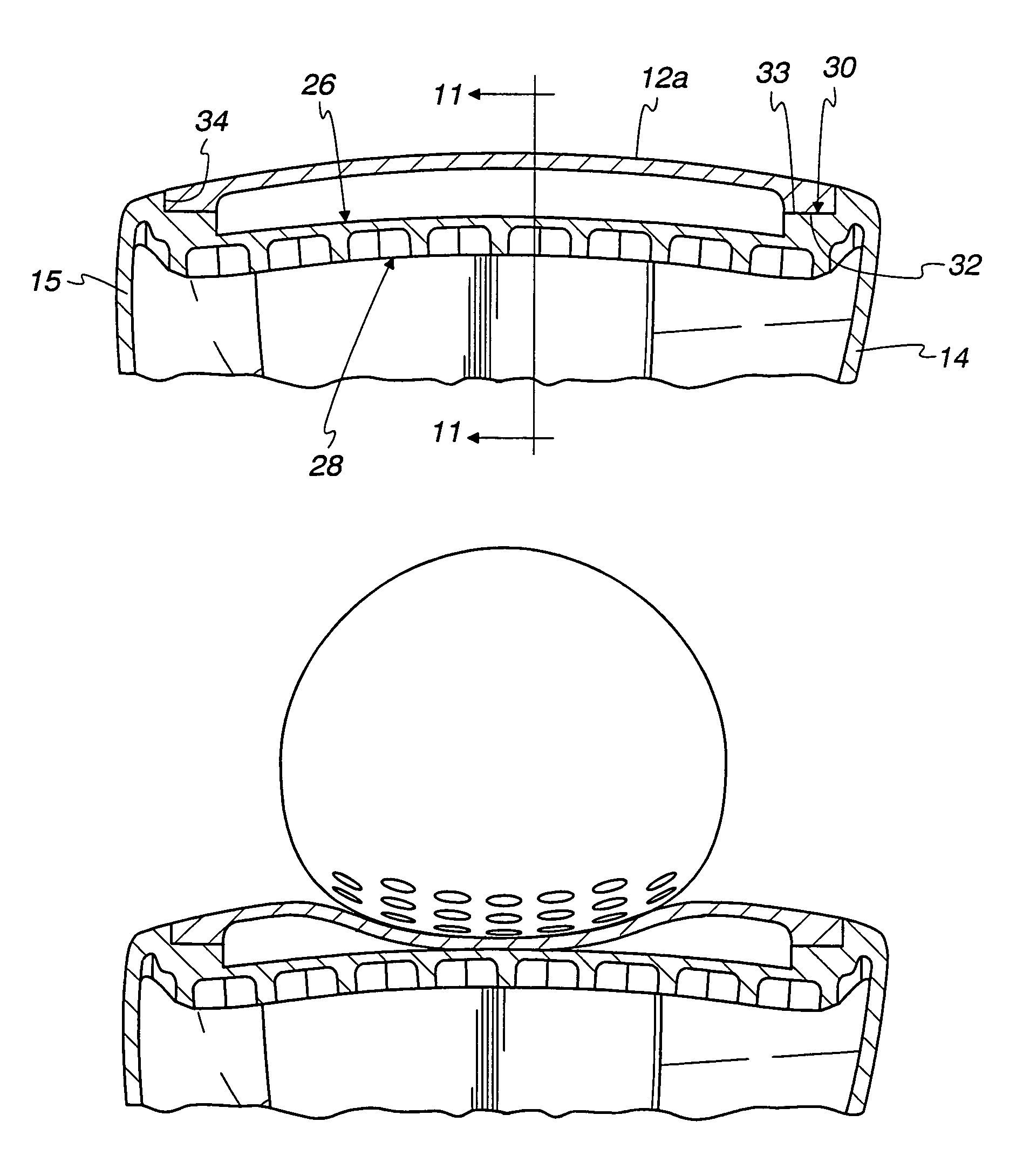
If rebound occurs after the ball exits the face wall, the benefits of this effect are completely lost.
None of the prior art dealing with these reinforcing elements suggests utilizing this technique for matching face wall rebound with ball exit from the face wall.
A further problem in the prior art references which suggest utilizing these rigidifying elements, is that they are completely silent on how these reinforcing elements, when not cast into the face wall, are attached into the club head.
Presently known bonding techniques are not sufficient to yield these benefits.
Still another of these prior references suggests making the head of synthetic material and the support rod of a similar material, but these low modulus and soft materials cannot significantly raise the resonant frequency or rebound time of the ball striking face wall.
First, the very large club heads spread the perimeter wall support points from the ball striking area, causing the face to flex more than smaller heads resulting in a badly delayed rebound of the face.
Secondly, while titanium is a hard material, it has a modulus of elasticity less than half that of ferrous alloys.
In these prior high titanium jumbo club heads however, the face wall does not fully recover until after the ball leaves the club face, thereby dissipating as waste a portion of the club head energy.
While others have attempted supports for other purposes such as face reinforcement and club sound or feel, they have not been successful because these clubs are either not possible to manufacture, or will fail under the rigors of a 100 to 150 ft. / sec. impact velocity against a golf ball.
While welding similar metals is certainly not a new concept, it is difficult to weld, for example, a 0.625 inch diameter shaft with a 0.035 to 0.049 inch wall thickness directly to the club head face wall and rear wall because the face wall and rear wall, because of their large areas, require higher heating and welding temperatures resulting in heat distortion of the face wall and rear club head.
As a manufacturing expedient, it is preferred to form the power shaft as a separate molding or forging because it is difficult to control the power shaft dimensional integrity when cast integrally with either the forward or rear piece.

Method used


Image

  • Golf club face flexure control system
  • Golf club face flexure control system
  • Golf club face flexure control system

Examples


Embodiment Construction

[0130]Referring to the drawings, it should be understood that FIGS. 1 to 16 relate to the new subject matter in the present application and that FIGS. 17 to 32 correspond to FIGS. 1 to 16 in parent application, U.S. Ser. No. 09 / 344,172, Filed: Jun. 24, 1999.

[0131]Referring initially to FIGS. 1 to 16, a club head 10 is illustrated according to the present invention that includes a standard body 11 and interchangeable face walls 12. The body 11 may be formed in forward and rear pieces as described in my U.S. Pat. No. 5,888,148.

[0132]The body 11 includes an upper crown wall 13, a toe wall 14, a heel wall 15, and a sole plate 17. An external portion 19 of the hosel assembly 20 shown in FIG. 4, projects upwardly from the crown wall 11.

[0133]The hosel assembly 20 includes an upper portion 21 and a spaced lower portion 22.

[0134]The crown wall 13, the toe wall 14, the heel wall 15, and the sole plate 17 together form the perimeter wall that surrounds the ball striking face wall 12.

[0135]As ...


PUM


Abstract

An improved line of golf clubs tailored to the golfer. The face wall firstly is designed so that the face wall modulus of elasticity increases from a low modulus for the low swing speed range to progressively higher modula for the higher swing speed ranges. Face modulus can be altered by a variety of techniques including face wall thinning, material selection and heat treatment or a combination thereof. In each of the swing speed range clubs, the face has a first modulus of elasticity determined by the face itself and after the face deflects to a predetermined value, the face modulus is significantly increased by a secondary wall parallel to and closely spaced behind the face wall.

Description

RELATED APPLICATION[0001]This application is a continuation-in-part of United States patent application entitled “GOLF CLUB FACE FLEXURE CONTROL SYSTEM”, U.S. Ser. No. 09 / 344,172, Filed: Jun. 24, 1999, now U.S. Pat. No. 6,354,961 B1, Issued: Mar. 12, 2002.BACKGROUND OF THE INVENTION[0002]The primary objective of the present invention is to design golf clubs for a variety of golfers that optimizes the distance the golfer impels the golf ball. To do this from a physics standpoint, it is necessary to obtain a maximum deflection of the ball striking face, or something approaching that maximum, during the collision with the ball while at the same time maintaining the other parameters of the golf club head within acceptable limits.[0003]This spring-like effect of the ball striking face, which is necessary to achieve maximum distance, has been widely misunderstood in the golf industry, even by many golf club designers. Many golf club designers believe that any deflection of the golf club f...

Claims


Application Information

Patent Timeline
Patent Type & Authority Patents(United States)
IPC IPC(8): A63B53/04
CPCA63B53/04A63B53/0466A63B2053/0416A63B2053/0433A63B2053/0408A63B2053/0458A63B2053/045A63B60/00A63B53/0408A63B53/0416A63B53/0433A63B53/045A63B53/0458
Inventor ALLEN, DILLIS V.
Owner KARSTEN MFG CORP
Why Eureka
Try Eureka