Charged particle beam system

a particle beam and beam system technology, applied in the field of charged particle beam tools, can solve the problems of limited structure size that can be produced, missing or excess pattern material of most newly fabricated masks, and affecting the quality of the mask, so as to achieve the effect of low gas pressur

Inactive Publication Date: 2005-12-27
FEI CO
View PDF16 Cites 54 Cited by
  • Summary
  • Abstract
  • Description
  • Claims
  • Application Information

AI Technical Summary

Benefits of technology

[0014]In some embodiments, an ion generator generates ions that neutralize charge on a work piece while maintaining a relatively low gas pressure in the vacuum chamber away from the ion generator. The pressure is sufficiently high at the ion generator to generate ions by collisions of secondary particles with the gas molecules, while being sufficiently low in the remainder of the vacuum chamber so that the time required to evacuate the system to a pressure suitable for operating a non-ESEM charged particle beam system is greatly reduced compared to the time required to evacuate the chamber from the operating pressure of the ESEM.

Problems solved by technology

The size of the structure that can be produced is limited by the wavelength of radiation used; shorter wavelengths can produce smaller structures.
Some photolithography masks for such short wavelengths use a reflective, rather than a transmissive, pattern on the mask because the mask substrate is not sufficiently transparent to such radiation of short wavelengths.
Most newly fabricated masks have defects such as missing or excess pattern material.
The electric charge adversely affects the operation of the charged particle beam by affecting the shape and positioning of the beam spot.
Such systems were not easy to use because they needed to be balanced for any change in operational conditions, or sample properties.
Increasing the gas pressure also increases the probability of a collision while traversing a particular path.
The relatively high gas pressure required for an ESEM detector makes such system unsuitable for use in the same vacuum chamber as another charged particle beam system, such as an ion beam system or a non-ESEM SEM, because most charged particle beam systems cannot operate at the relatively high gas pressures required by an ESEM.
The gas molecules interfere with the ions or electrons in the beam, reducing resolution or degrading signal to noise ratio.

Method used


Image

  • Charged particle beam system
  • Charged particle beam system
  • Charged particle beam system

Examples


Embodiment Construction

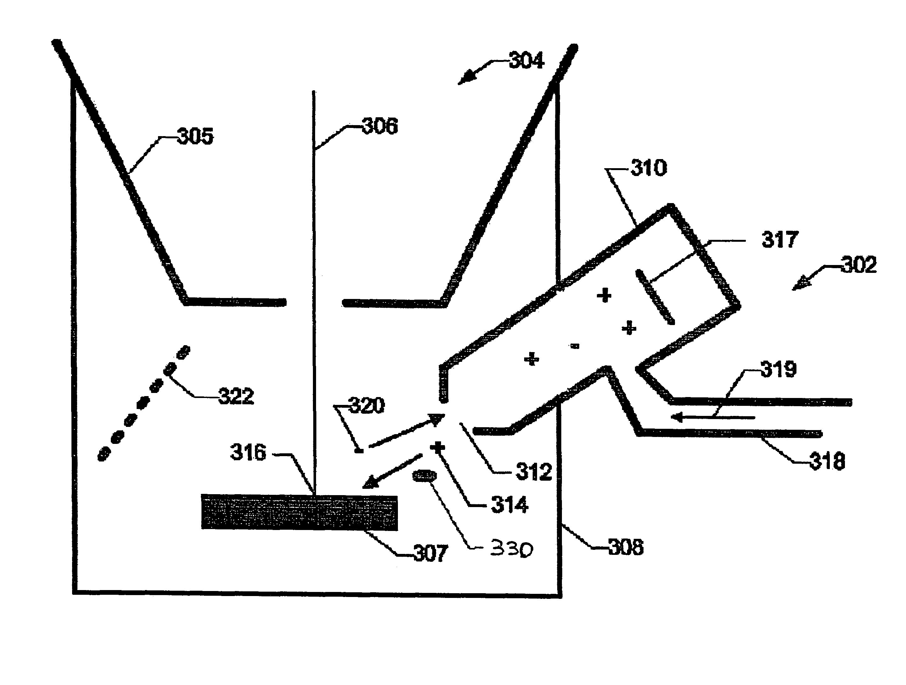
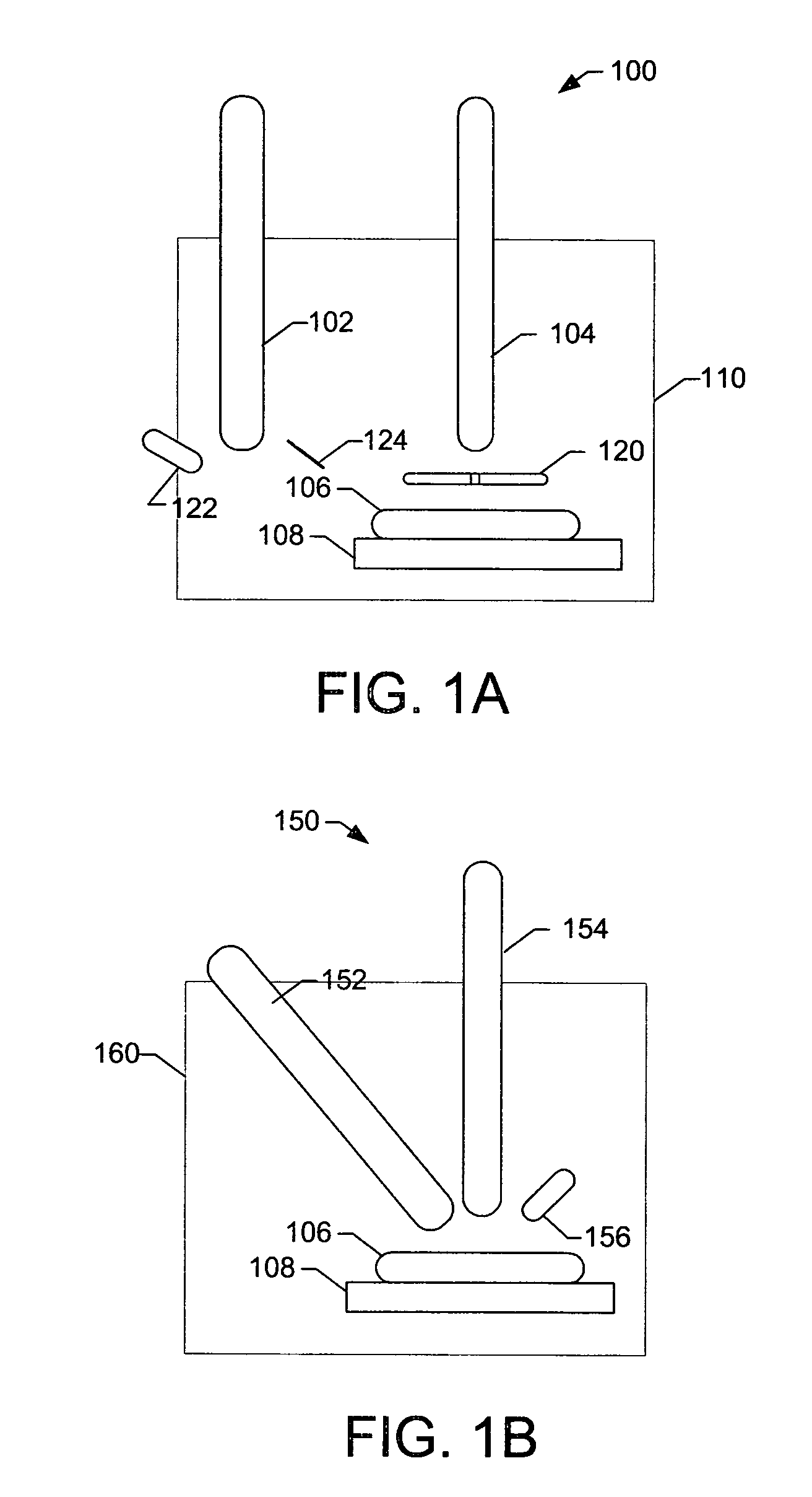
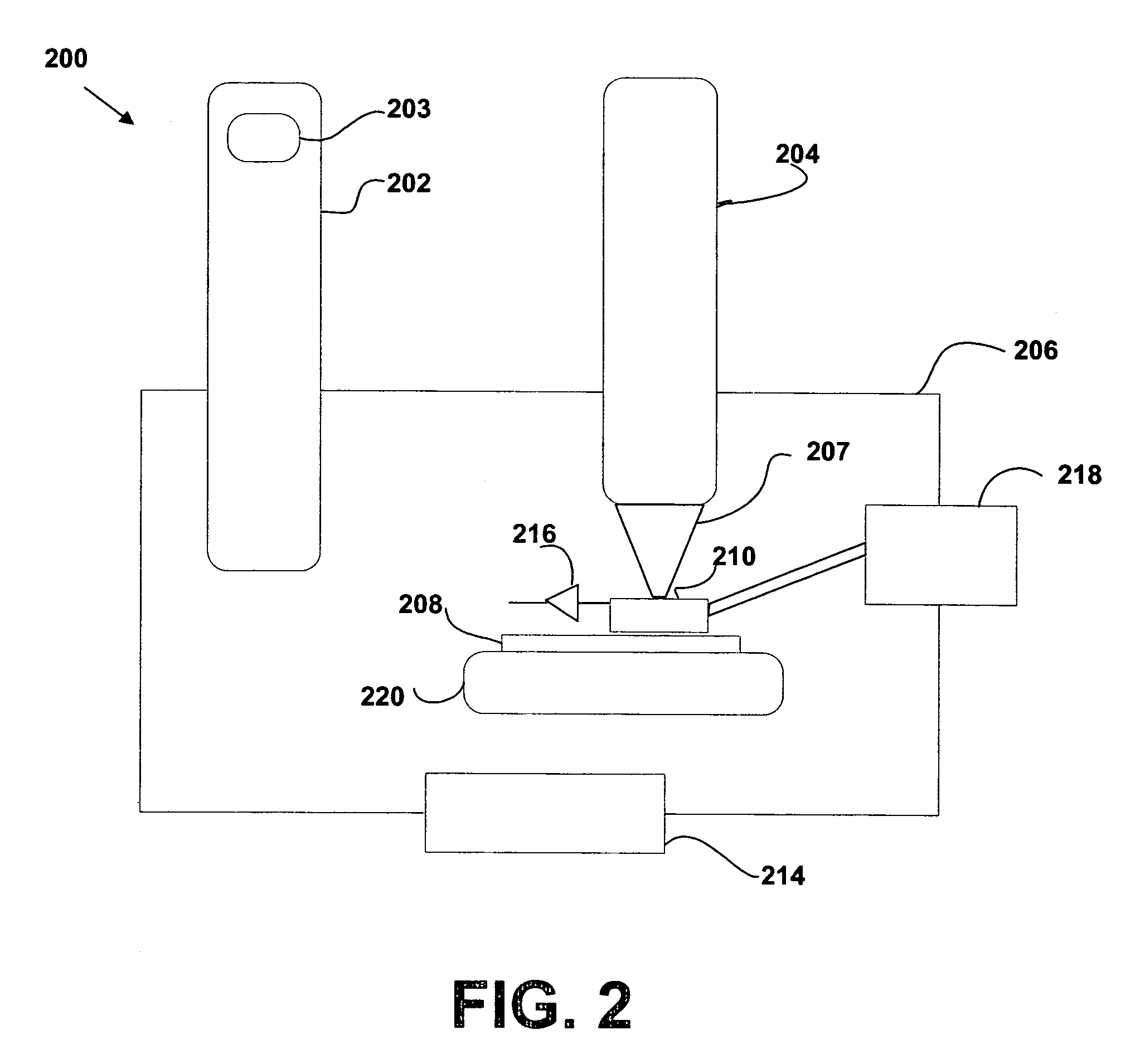
[0031]A preferred embodiment of the invention uses an ion generator to neutralize negative charge in insulating samples in a charged particle beam system. Because photolithography masks are typically fabricated on an insulating substrate, such as quartz, the invention is useful for charged particle beam operations on photolithography masks.

[0032]The ion generator preferably uses secondary or backscattered electrons emanating from the work piece to ionize a gas, in a manner similar to the way a detector works in an environmental scanning electron microscope (ESEM). The secondary particles collide with and ionize the gas molecules as the particles pass through the gas, producing free electrons which then collide with and ionize other gas molecules in a cascading reaction. This ion generation process can generate large quantities of ions for use in stabilizing the charge on insulating samples or for imaging.

[0033]By using secondary particles from the work piece to generate the ions, th...


PUM

PropertyMeasurementUnit
pressureaaaaaaaaaa
pressureaaaaaaaaaa
pressureaaaaaaaaaa

Abstract

A charged particle beam system uses an ion generator for charge neutralization. In some embodiments, the ion generator is configured to maintain an adequate gas pressure at the ion generator to generate ions, but a reduced pressure in the remainder of the vacuum chamber, so that another column can operate in the chamber either simultaneously or after an evacuation process that is much shorter than a process that would be required to evacuate the chamber from the full pressure required at the ion generator. The invention is particularly useful for repair of photolithography masks in a dual beam system.

Description

[0001]This application is a continuation-in-part of U.S. patent application Ser. No. 10 / 665,398, filed on Sep. 18, 2003, now abandoned which is hereby incorporated by reference, which claims priority from U.S. Prov. Pat. App. No. 60 / 411,699, filed Sep. 18, 2002, and which is a continuation-in-part of U.S. patent application Ser. No. 10 / 330,691, filed on Dec. 27, 2002 now abandoned.TECHNICAL FIELD OF THE INVENTION[0002]The present invention relates to the field of charged particle beam tools for forming, altering and viewing microscopic structures.BACKGROUND OF THE INVENTION[0003]Photolithography is a process that is used to create small structures, such as integrated circuits and micromachines. The photolithography process entails exposing a radiation-sensitive substance, called photoresist, to a pattern of light or other radiation. The pattern is typically created by passing the radiation through a mask, that is, a substrate having a pattern on the surface. The pattern blocks some ...

Claims


Application Information

Patent Timeline
Patent Type & Authority Patents(United States)
IPC IPC(8): G01N23/00G01N23/225H01J37/02H01J37/252H01J37/244H01J37/28H01J37/317H01L21/027
CPCG01N23/225H01J37/244H01J2237/0045H01J2237/2817H01J2237/31737H01J2237/31742H01J2237/31798
Inventor STEWART, DIANE K.KNOWLES, W. RALPHKIMBALL, BRIAN T.
Owner FEI CO
Why Eureka
Try Eureka