
Duplexer and communication apparatus with a matching circuit including a trap circuit for harmonic suppression

a matching circuit and harmonic suppression technology, applied in the field of branching filters, can solve the problems of harmonics, low surge resistance, damage to the saw filter, etc., and achieve the effect of high surge resistan

Active Publication Date: 2006-01-03
MURATA MFG CO LTD
View PDF15 Cites 14 Cited by
  • Summary
  • Abstract
  • Description
  • Claims
  • Application Information

AI Technical Summary

Benefits of technology

The present invention provides a duplexer that can suppress harmonics without adding any additional components or increasing the size of the duplexer. The duplexer includes a transmitting filter, a receiving filter, and a matching circuit that functions as a trap circuit for harmonic suppression. The matching circuit prevents mutual interference between the filters when the antenna is shared between the transmitter and the receiver. The duplexer also includes a parallel inductor connected between the antenna terminal and a ground to control the capacitance of the matching circuit and protect the receiving filter from surge currents. The open stub in the matching circuit functions as a trap circuit for harmonic suppression. The duplexer is compact and achieves stable transmission and reception properties. The matching circuit has a high-Q parallel inductor to improve the characteristics of the duplexer. The duplexer is housed in a package or a multi-layer substrate for easy control and improved characteristics. The parallel inductor is a chip coil or a high-Q inductor, which further reduces the size of the duplexer. The duplexer includes a package for housing the filters and the matching circuit, which further reduces the size of the duplexer. The parallel inductor is a spiral microstrip line or a short stub built in the multi-layer substrate. The duplexer improves surge resistance with the use of a ladder-type SAW filter or a SAW filter with improved surge resistance. The communication apparatus includes the duplexer with these features.

Problems solved by technology

Such harmonics are also emitted from the antenna which thus causes noise.
However, duplexers using a SAW filter also have a problem in that harmonics (second, third, .
The harmonics input from the PA 61 also passes through the SAW filter which leads to noise.
Another problem is that the electrode pitch of the SAW filter is very narrow, such as submicron to 2 μm, which results in low surge resistance.
Incoming static electricity from the antenna during cellular phone use can damage the SAW filter, and ESD (electrostatic discharge) protection is therefore required.
If the duplexer includes an additional protection circuit for improving the surge resistance of the SAW filters, the number of components, such as the isolator and the protection circuit, increases and the duplexer size inevitably increases.
The duplexer disclosed in this publication does not provide ESD protection.
However, this electrostatic protection circuit does not provide harmonic suppression, and thus, requires an additional trap circuit for harmonic suppression.

Method used


Image

  • Duplexer and communication apparatus with a matching circuit including a trap circuit for harmonic suppression
  • Duplexer and communication apparatus with a matching circuit including a trap circuit for harmonic suppression
  • Duplexer and communication apparatus with a matching circuit including a trap circuit for harmonic suppression

Examples


first preferred embodiment

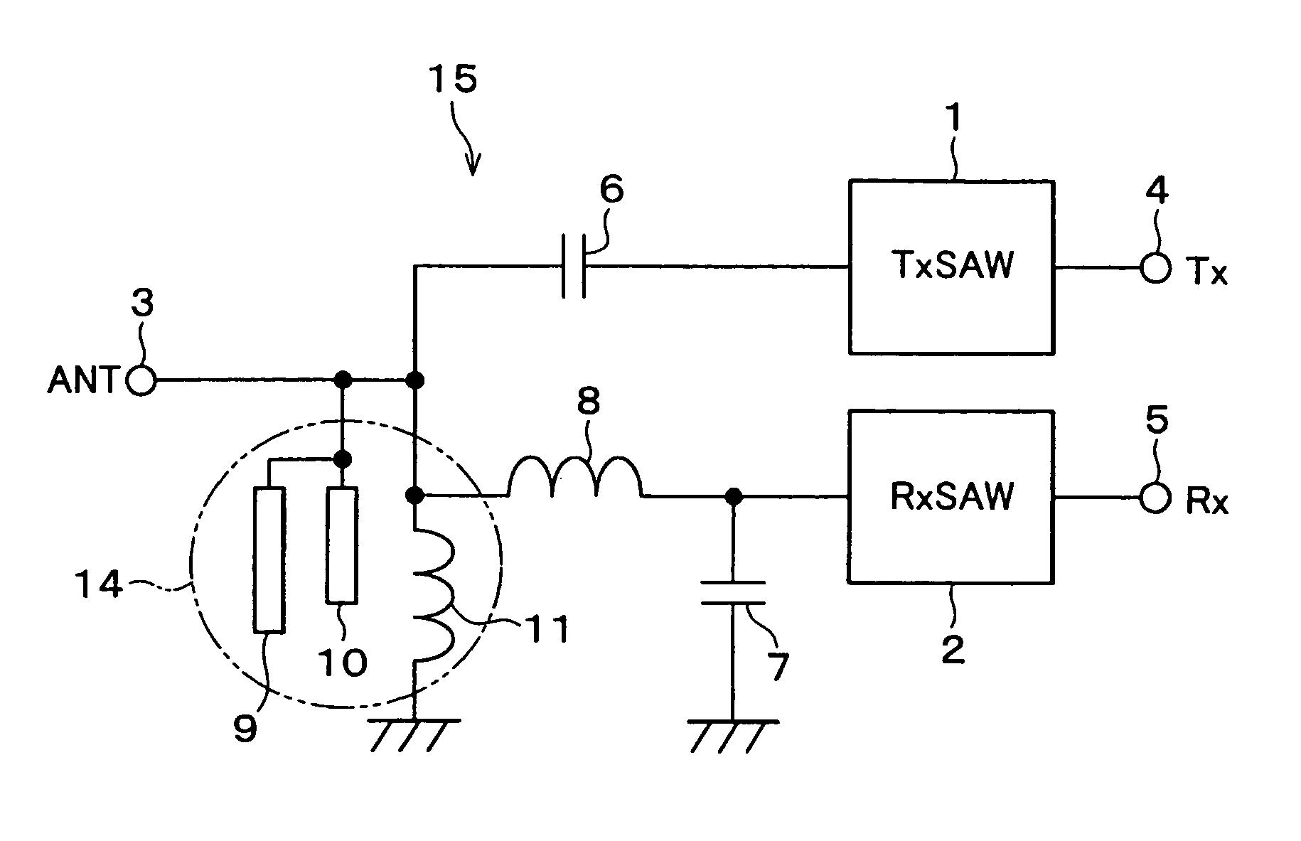
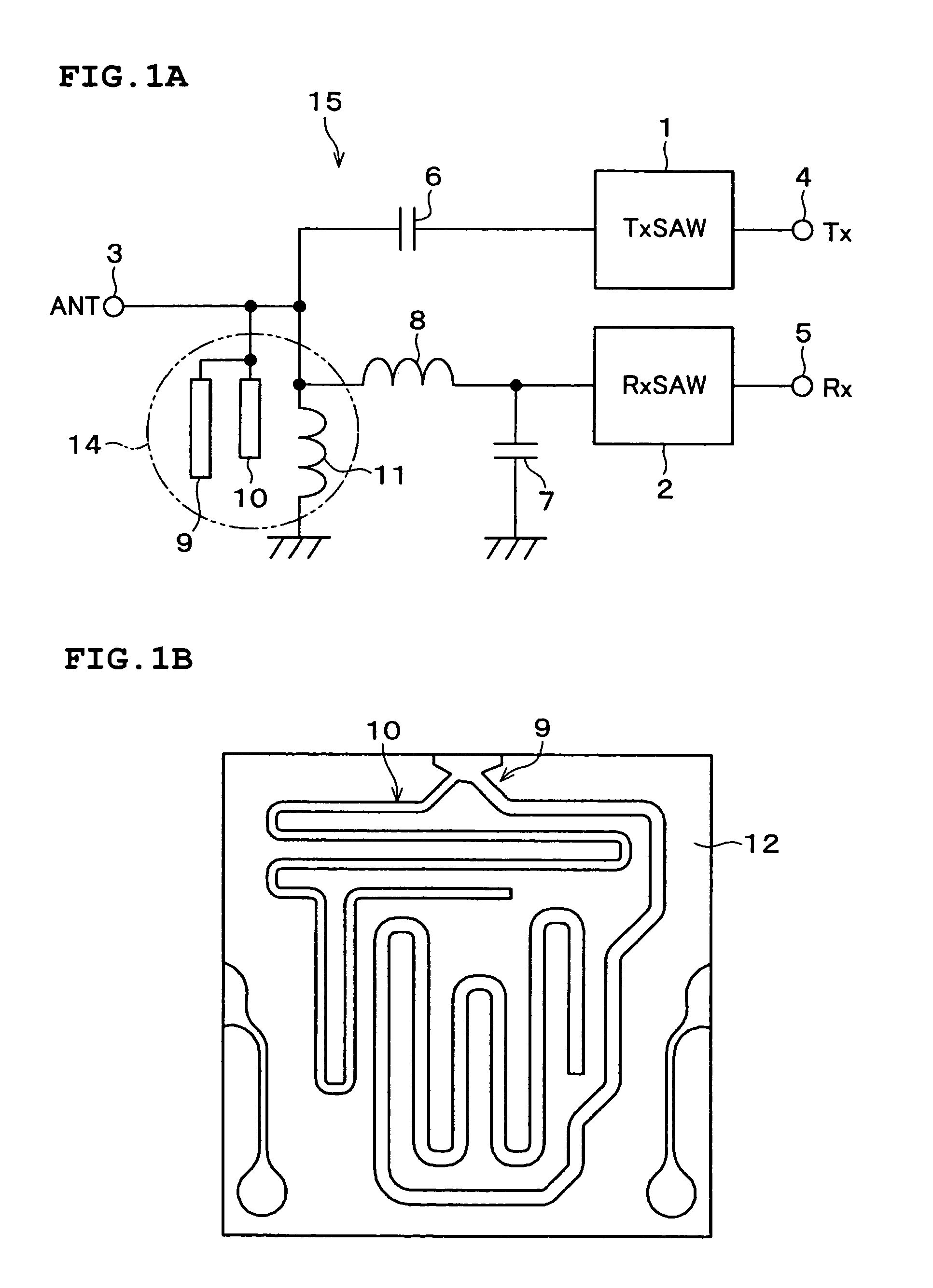
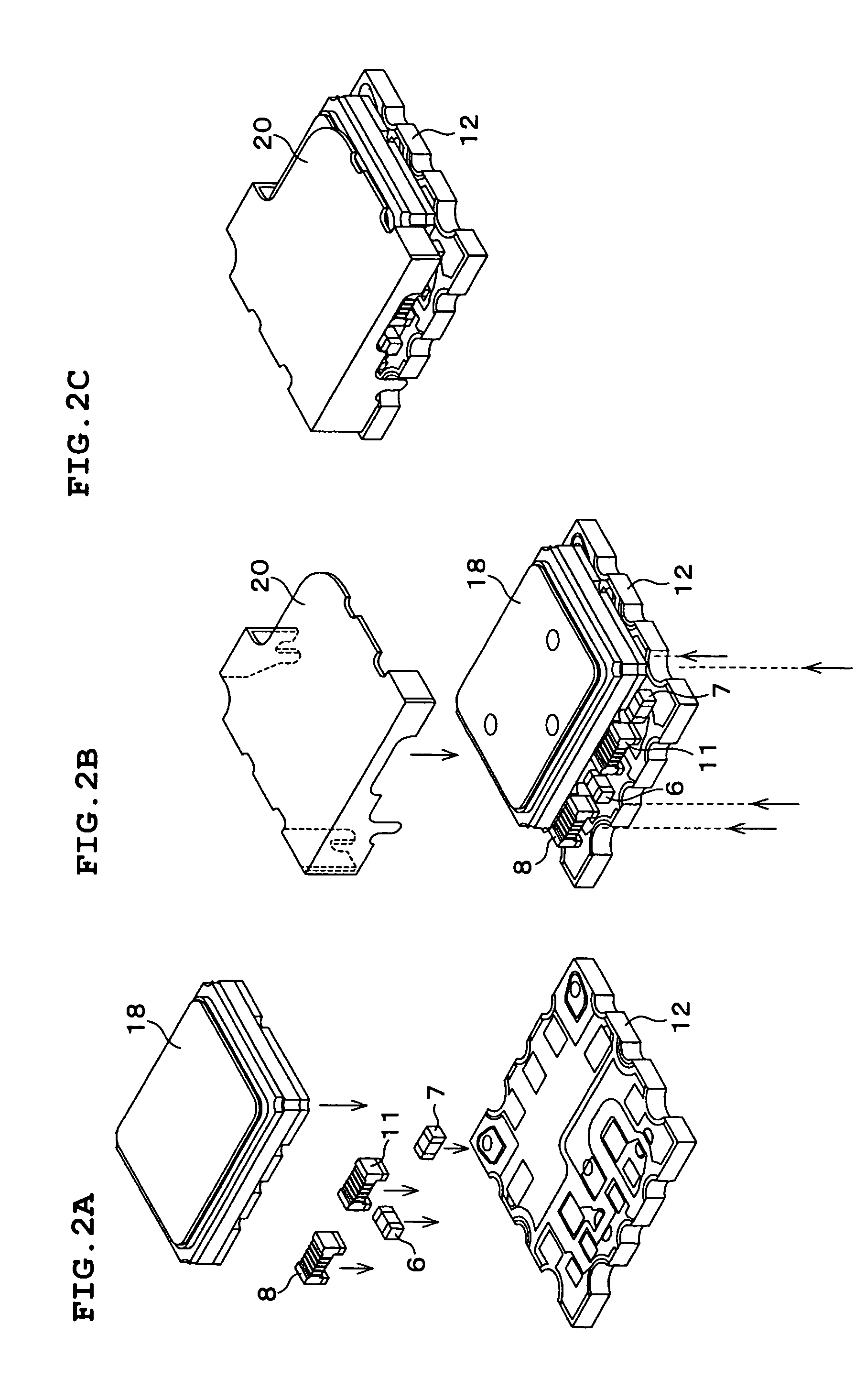
[0049]FIG. 1A is a circuit diagram of a duplexer according to a first preferred embodiment of the present invention, and FIG. 1B is a plan view of open stubs of the duplexer. FIGS. 2A through 2C are external perspective views of the duplexer according to the first preferred embodiment, showing the assembly procedure.

[0050]As shown in FIG. 1A, the duplexer includes an input terminal 4 to which a transmission (Tx) signal is input, an output terminal 5 from which a received (Rx) signal is output, and an antenna (ANT) terminal 3 defining a shared input / output terminal to which the transmission signal is input and from which the received signal is output.

[0051]The duplexer further includes Tx-signal and Rx-signal band-pass filters (BPFs), which are defined by T-shaped ladder SAW filters each having series resonators on the input and output sides, respectively, namely, a Tx SAW filter 1 and an Rx SAW filter 2.

[0052]The Tx SAW filter 1 is connected between the antenna terminal 3 and the in...

second preferred embodiment

[0068]A duplexer according to a second preferred embodiment of the present invention will now be described with reference to FIGS. 3A through 4C. In the second preferred embodiment, components having similar functions to those of the first preferred embodiment are given the same reference numerals, and a description thereof is omitted.

[0069]The duplexer according to the second preferred embodiment includes a microstrip-line parallel inductor 16, in place of the parallel inductor 11 defined by a wound-type chip coil in the first preferred embodiment, as shown in FIG. 3A.

[0070]The microstrip-line parallel inductor 16 which is short-circuited to a ground is also referred to as a short stub, a half-wavelength line, or a short-circuited stub, and inherently attenuates a certain characteristic frequency. In the second preferred embodiment, however, the parallel inductor 16 functions only as an inductor.

[0071]In general, short stubs are inductive at frequencies that are lower than the anti...


PUM


Abstract

A duplexer includes a transmitting filter and a receiving filter which are connected in parallel to an antenna terminal, and a matching circuit connected between the antenna terminal and at least one of the transmitting filter and the receiving filter. A portion of the matching circuit defines a trap circuit for harmonic suppression.

Description

BACKGROUND OF THE INVENTION[0001]1. Field of the Invention[0002]The present invention relates to a branching filter (duplexer) using a surface acoustic wave (SAW) filter, and more particularly, to a branching filter which provides harmonic suppression and high surge resistance without increasing the number of components and the size of the device, and also relates to a communication apparatus including the duplexer.[0003]2. Description of the Related Art[0004]With the recent popularity of mobile communication devices, such as cellular phones, the demand for thinner and smaller cellular phones with stable operation, e.g., with fewer malfunctions over time, has increased.[0005]Such cellular phones share an antenna between the transmitter and the receiver in order to reduce the size. The cellular phones include a branching filter (hereinafter referred to as a duplexer or DPX) for separating a transmission high-frequency signal and a reception high-frequency signal whose center frequenc...

Claims


Application Information

Patent Timeline
Patent Type & Authority Patents(United States)
IPC IPC(8): H03H9/70H03H9/72H01P1/203H01P1/213H01P7/08H03H7/38H03H7/46H03H9/64H04B1/52
CPCH01P1/2135H03H9/0576H04B1/525H04B1/52H03H2001/0078H03H9/72
Inventor SAKANO, KIWAMU
Owner MURATA MFG CO LTD
Learn More