Light emitting diode (LED) array for excitation emission matrix (EEM) fluorescence spectroscopy

an excitation emission and fluorescence spectroscopy technology, applied in the field of single measurement excitation emission matrix (eem) spectroscopy, can solve the problems of inability to easily collect full emission spectra for several excitation wavelengths, generally required expensive and complex instrumentation, etc., and achieves low component cost, convenient use, and low power requirements

Inactive Publication Date: 2006-01-10
THE UNITED STATES OF AMERICA AS REPRESENTED BY THE SECRETARY OF THE NAVY
View PDF7 Cites 35 Cited by
  • Summary
  • Abstract
  • Description
  • Claims
  • Application Information

AI Technical Summary

Benefits of technology

[0014]Another object of the invention is to provide an LED array EEM spectroscopic system whose results are comparable to exi

Problems solved by technology

The ability to easily collect full emission spectra for several excitation

Method used


Image

  • Light emitting diode (LED) array for excitation emission matrix (EEM) fluorescence spectroscopy
  • Light emitting diode (LED) array for excitation emission matrix (EEM) fluorescence spectroscopy
  • Light emitting diode (LED) array for excitation emission matrix (EEM) fluorescence spectroscopy

Examples


Embodiment Construction

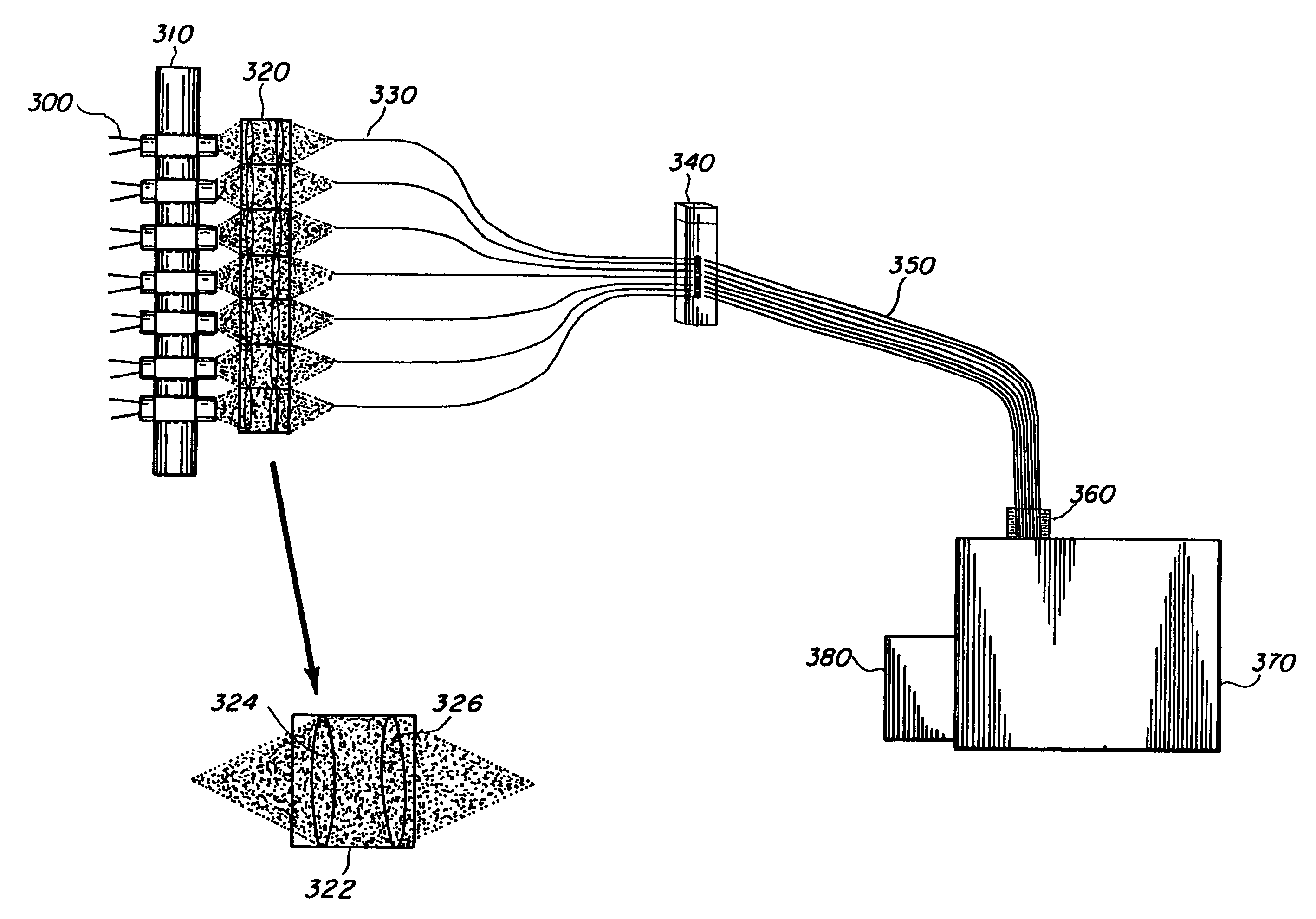
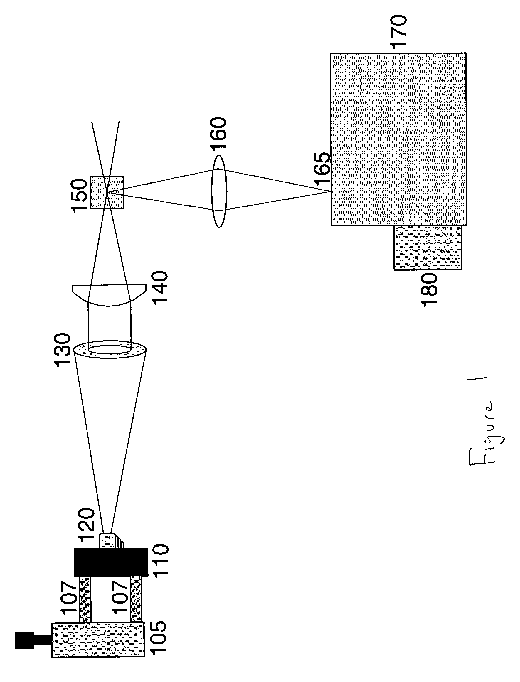
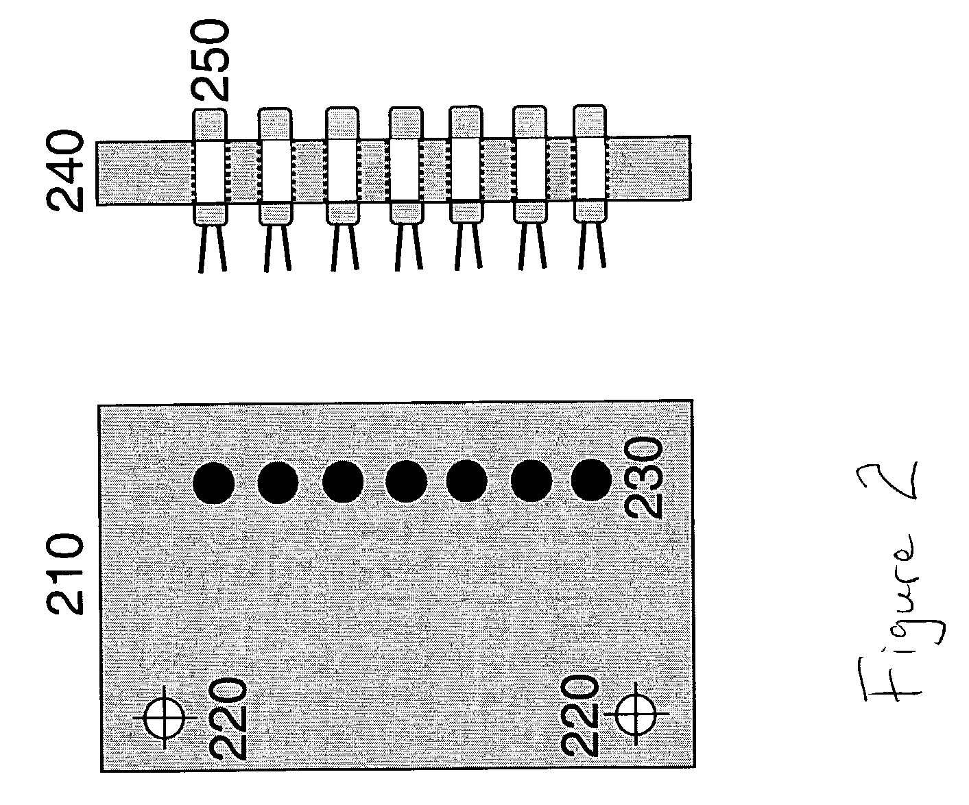
[0023]This invention represents a new instrument for single measurement EEM spectroscopy which is based upon an array of light emitting diodes (LED). The array of LEDs is focused into a sample cuvette, creating spatially separated excitation spots. LED-induced fluorescence from analytes in solution is collected at right angles and delivered to the entrance of a spectrograph with a CCD camera for detection. The broad emission spectrum of LEDs permits continuous coverage over a large excitation range with a limited number of LEDs, allowing excitation of all analytes with absorption within the LED's excitation range. Each analyte may be uniquely excited by each LED, thereby conserving the multi-way characteristics of the data common to all EEM methods. In this regard, LED-EEM spectroscopy can be viewed from a sensors standpoint: multiple partially selective instrumental elements. These individual components, when combined, provide a more complete spectroscopic picture of the chemical p...


PUM


Abstract

This invention discloses an Excitation Emission Matrix (EEM) fluorescence spectrometer system that uses an LED array to cause excitation emission matrix fluorescence that is imaged onto a spectrograph for sample identification and analysis. By using the LED array, the spectrograph requires only high spectroscopic resolution of about 1 to 5 nm in the fluorescence emission range and low excitation light resolution of about 14 to 73 nm in the excitation range. While individual LED optical excitation spectra may contain wavelength regions that overlap, as long as the various LEDs have different excitation wavelengths and intensities, spectral overlap does not preclude data analysis. The invention provides an EEM spectroscopy system that is not a high resolution such as a laser or lamp based excitation system, but instead uses a lower resolution, lower power LED system. The invention also provides results that are comparable to existing systems with lower component cost and lower power requirements while also optically stable, small, and easy to use.

Description

BACKGROUND OF THE INVENTION[0001]1. Field of the Invention[0002]The invention is concerned with single measurement Excitation Emission Matrix (EEM) spectroscopy using an array of light emitting diodes (LED). The array of LEDs is focused into a sample cuvette, creating spacially separated excitation spots.[0003]2. Description of the Related Prior Art[0004]Fluorescence excitation emission matrix (EEM) spectroscopy has long been known as a powerful method for complex mixture analysis. (See Hershberger, L. W.; Callis, J. B.; Christian, G. D.; Anal. Chem., 1981, 53, 971–975; Skoropinski, B.; Callis, J. B.; Danielson, J. D. S.; Christian G. D.; 1986, Anal. Chem., 58, 2831–2839; and Jalkian, R.; Denton, B.; Proc. SPIE 1989, 1054, 91–102.)[0005]The ability to easily collect full emission spectra for several excitation wavelengths, has generally required expensive and complex instrumentation. The multi-way characteristics of EEM data enable the extraction of the salient chemical features. As...

Claims


Application Information

Patent Timeline
IPC IPC(8): G01J3/30G01J3/02G01J3/10G01J3/44G01N21/64
CPCG01J3/02G01J3/4406G01J3/10G01J3/0218
Inventor HART, SEAN J.
Owner THE UNITED STATES OF AMERICA AS REPRESENTED BY THE SECRETARY OF THE NAVY
Why Eureka
Try Eureka