Unlock instant, AI-driven research and patent intelligence for your innovation.

Light detection and imaging system and method including an array of sensors

Active Publication Date: 2006-01-17
PALO ALTO RES CENT INC
View PDF3 Cites 12 Cited by
  • Summary
  • Abstract
  • Description
  • Claims
  • Application Information

AI Technical Summary

Benefits of technology

[0018]In various exemplary embodiments, the systems and methods further provide increased performance at a lower cost as compared to the conventional methods discussed above because a single illumination source may efficiently illuminate an object and a plurality of sensors, for example, an array of sensors without using an objective lens.
[0019]In various alternative embodiments of the invention, optical filters may be used to effectively absorb the primary illumination allowing the fluorescence light at a different wavelength to pass through the filter and be detected by the sensor. The filters may be integrated onto a sensor chip in order to reduce the resulting size of the system and overall costs. Moreover, baffles may be used to improve the detection of the light from the object.

Problems solved by technology

Conventional methods that use a single detector such as a single PMT to detect light, or illuminate the object broadly and detect the light using a pixel array may not properly detect the emitted fluorescence light.
For example, the detection using these methods may be unsatisfactory and relatively slow because a single detector is used in the device with the PMT.
Moreover, a weak signal may result when broadly scanning the pixel array thus making detection of the light even more difficult.
However, conventional arrangements using the silicon photodiodes have a relatively flat response over the entire visible spectrum.
Moreover, conventional arrangements of silicon diodes as sensors may also produce a considerable amount of noise, (much of it thermal) resulting in relatively poor signal-to-noise under photon-limited conditions.
However, conventional devices do not properly detect the emitted fluorescence light in this manner using conventional sensor arrangements.
However, in these systems, not all of the light is collected and detected, which poses a particular problem if the angular distribution of the emission is large.
Moreover, the time required to accurately detect using this system is excessive.
When the detection device uses the PMT imager scanned across the plate, or a charge-coupled device (CCD) to image a line, the time necessary for imaging is excessive.
However, this method is disadvantageous because the illumination at any given cell is generally very-weak, and the optical coupling between the object and detector may be unsatisfactory when a large field of view is needed.
If the conventional fluorescence detection device includes PMTs, CCDs, optical filters, lenses and lasers, the detection system may tend to be bulky resulting in problems that can arise because of the size of the detections systems.
However, the detection systems of the prior techniques pose many problems in the efficiency of sequencing and imaging.
Further, by using a prior art detector, all of the possible data may not be collected.
Another reason that the prior art detection systems are not efficient is that these systems typically only detect one band at a time, e.g. the band that has reached the end of the separation apparatus in fixed end detection.

Method used


Image

  • Light detection and imaging system and method including an array of sensors
  • Light detection and imaging system and method including an array of sensors
  • Light detection and imaging system and method including an array of sensors

Examples


Embodiment Construction

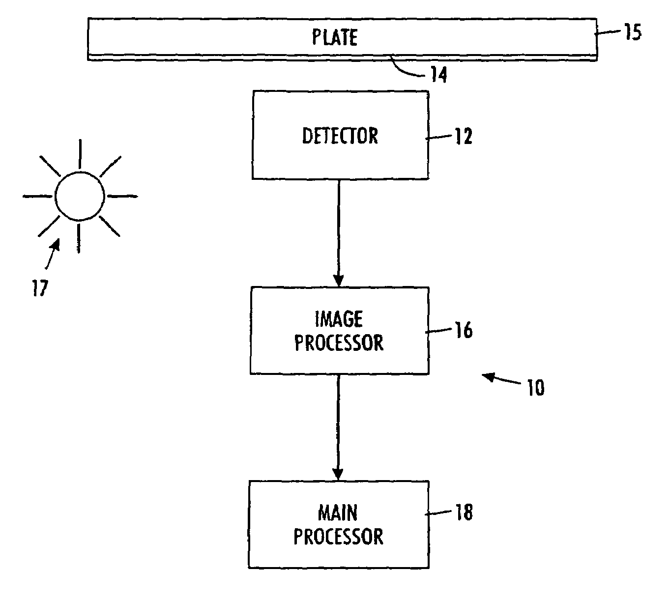
[0032]The invention relates generally to systems and methods of imaging an object using a scanned array of detectors operated by imaging. With reference now to the drawings wherein the showings (which generally only representatively show the elements) are for purposes of illustrating the features of the invention and not for purposes of limiting the same, FIG. 1 shows a system 10 for imaging an object or a sample. A detector 12 detects the emission of light from a sample or object 14 disposed on a substrate that may include a plate 15. After an illumination source 17 illuminates the object 14, the detector 12 scans the entire plate 15 at predetermined points in time to obtain the necessary data. The data collected by the detector 12 (which represents an image of a region of interest on the object 14 at a given time) is then processed by an image processor 16. Based on the resultant processed data provided by the image processor 16, an image is created.

[0033]The detector may sense fl...


PUM


Abstract

A light detection system for imaging an object including a light source, an object, a first substrate with a sensor arranged on a side of the first substrate opposite from the light source, the sensor having an opening through which the light from the light source passes. A distance from the sensor to the object corresponds approximately to the size of the sensor. The light illuminates the object and the sensor detects the light emanating from the object. The object is scanned relative to the sensor to create the image. A method includes arranging the sensor to face the object, illuminating the object with a light source so that the light passes through the opening in the sensor, and detecting the light emanating from the object, the object being scanned relative to the sensor to create the image.

Description

BACKGROUND OF THE INVENTION[0001]1. Field of Invention[0002]The invention relates to systems and methods for detecting light using a sensor. More specifically, the systems and methods of the invention relate to an imaging detector that includes an array of sensors.[0003]2. Description of Related Art[0004]Fluorescence illumination and observation is a rapidly expanding microscopy technique employed today. This microscopy technique may be used in both the medical and biological sciences. Because the microscopy technique is rapidly expanding, sophisticated microscopes and numerous fluorescence accessories have been developed. For example, Epi-fluorescence, or incident light fluorescence, is used in many applications. The technique of fluorescence microscopy has become an essential tool in biology and the biomedical sciences, as well as in materials science due to attributes that are not readily available in other contrast modes with traditional optical microscopy. The application of an...

Claims


Application Information

Patent Timeline
IPC IPC(8): G01N21/64
CPCG01N21/6456G02B21/002G01N21/6458
Inventor STREET, ROBERT A.MAEDA, PATRICK Y.
Owner PALO ALTO RES CENT INC