Optical film with co-continuous phases

a phase-continuous phase, optical film technology, applied in the field of optical materials, can solve the problem of significant diffuse reflection, achieve the effect of large optical anisotropy, reduce the contribution of scattered light outside of this plane, and reduce scattering strength

Inactive Publication Date: 2006-01-17
3M INNOVATIVE PROPERTIES CO
View PDF137 Cites 30 Cited by
  • Summary
  • Abstract
  • Description
  • Claims
  • Application Information

AI Technical Summary

Benefits of technology

[0167]The value of off-angle-color (OAC) demonstrates the advantage of using a multilayer construction within the context of the present invention. In particular, such a construction can be used to substantially reduce OAC with only a modest reduction in gain. This tradeoff may have advantages in some applications. The values of T♀ for the examples of the invention may be lower than expected because light scattered by the sPS dispersed phase may not be received by the detector.

Problems solved by technology

Incident light polarized along, or parallel to, a mismatched axis is scattered, resulting in significant diffuse reflection.

Method used


Image

  • Optical film with co-continuous phases
  • Optical film with co-continuous phases
  • Optical film with co-continuous phases

Examples


example 1

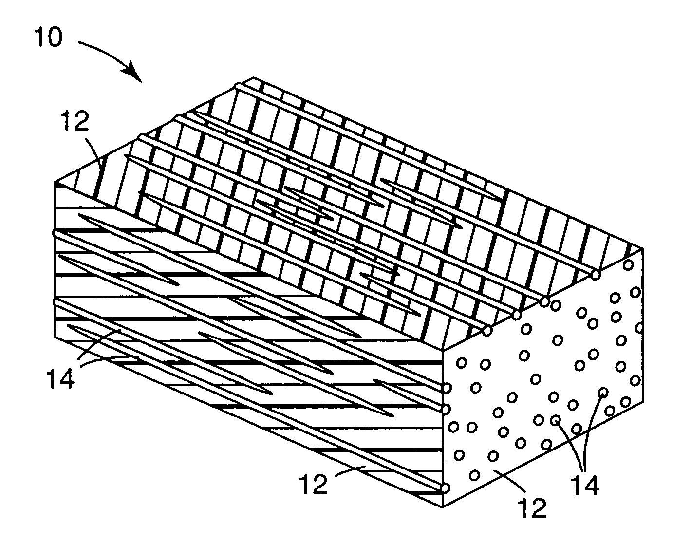
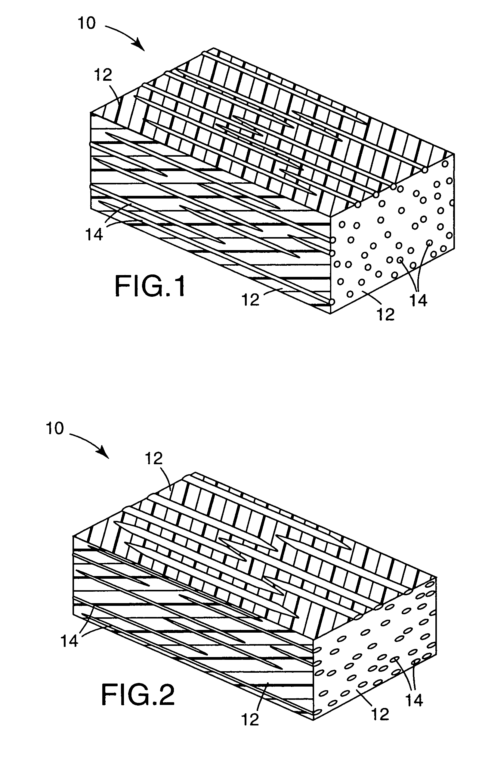
[0134]In Example 1, an optical film was made in accordance with the invention by extruding a blend of 75% polyethylene naphthalate (PEN) as the continuous or major phase and 25% of polymethylmethacrylate (PMMA) as the disperse or minor phase into a cast film or sheet about 380 microns thick using conventional extrusion and casting techniques. The PEN had an intrinsic viscosity (IV) of 0.52 (measured in 60% phenol, 40% dichlorobenzene). The PMMA was obtained from ICI Americas, Inc., Wilmington, Del., under the product designation CP82. The extruder used was a 3.15 cm (1.24″) Brabender with a 1 tube 60 μm Tegra filter. The die was a 30.4 cm (12″) EDI Ultraflex™ 40.

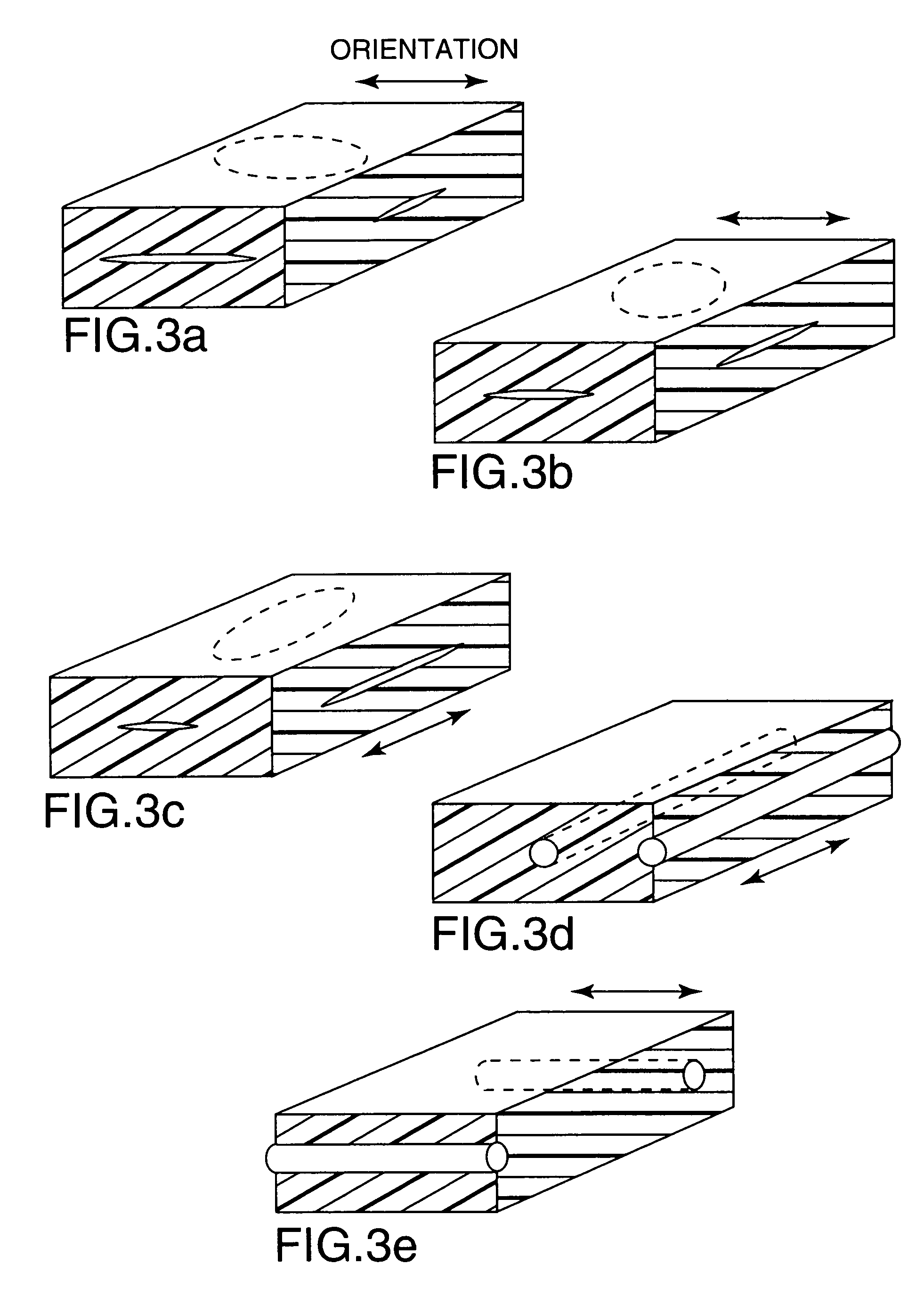
[0135]About 24 hours after the film was extruded, the cast film was oriented in the width or transverse direction (TD) on a polyester film tentering device. The stretching was accomplished at about 9.1 meters per minute (30 ft / min) with an output width of about 140 cm (55 inches) and a stretching temperature of about 160° C....

example 2

[0136]In Example 2, an optical film was made and evaluated in a manner similar to Example 1 except using a blend of 75% PEN, 25% syndiotactic polystyrene (sPS), 0.2% of a polystyrene glycidyl methacrylate compatibilizer, and 0.25% each of Irganox™ 1010 and Ultranox™ 626. The synthesis of polystyrene glycidyl methacrylate is described in Polymer Processes, “Chemical Technology of Plastics, Resins, Rubbers, Adhesives and Fibers”, Vol. 10, Chap. 3, pp. 69–109 (1956)(Ed. by Calvin E. Schildknecht).

[0137]The PEN had an intrinsic viscosity of 0.52 measured in 60% phenol, 40% dichlorobenzene. The sPS was obtained from Dow Chemical Co. and had a weight average molecular weight of about 200,000, designated subsequently as sPS-200-0. The parallel reflectivity on the stretched film sample was determined to be 73.3%, and the crossed reflectivity was determined to be 35%.

example 3

[0138]In Example 3, an optical film was made and evaluated in a manner similar to Example 2 except the compatibilizer level was raised to 0.6%. The resulting parallel reflectivity was determined to be 81% and the crossed reflectivity was determined to be 35.6%.


PUM

PropertyMeasurementUnit
specular angleaaaaaaaaaa
vertex angleaaaaaaaaaa
scattering angleaaaaaaaaaa

Abstract

An optical film is provided which comprises a disperse phase of polymeric particles disposed within a continuous birefringent matrix. The film is oriented, typically by stretching, in one or more directions. The size and shape of the disperse phase particles, the volume fraction of the disperse phase, the film thickness, and the amount of orientation are chosen to attain a desired degree of diffuse reflection and total transmission of electromagnetic radiation of a desired wavelength in the resulting film.

Description

CROSS REFERENCE TO RELATED APPLICATION[0001]This is a continuation application of U.S. application Ser. No. 08 / 801,329, filed Feb. 18, 1997, Now U.S. Pat. No. 6,590,705 now allowed, which is a continuation-in-part of U.S. application Ser. No. 08 / 610,110, filed Feb. 29, 1996, now abandoned, the disclosure of which is herein incorporated by reference.FIELD OF THE INVENTION[0002]This invention relates to optical materials which contain structures suitable for controlling optical characteristics, such as reflectance and transmission. In a further aspect, it relates to control of specific polarizations of reflected or transmitted light.BACKGROUND[0003]Optical films are known to the art which are constructed from inclusions dispersed within a continuous matrix. The characteristics of these inclusions can be manipulated to provide a range of reflective and transmissive properties to the film. These characteristics include inclusion size with respect to wavelength within the film, inclusion...

Claims


Application Information

Patent Timeline
Patent Type & Authority Patents(United States)
IPC IPC(8): G02B5/30B32B3/26C08J5/00B29C55/02B29K25/00B29K67/00B29L7/00B29L11/00C08J5/18C08L25/00C08L67/02G02B1/04G02B1/08
CPCG02B1/04G02B5/3083G02B5/305G02B5/3008Y10T428/249955Y10T428/249953
Inventor ALLEN, RICHARD C.KOTZ, ARTHUR L.CARLSON, LOCKWOOD W.NEVITT, TIMOTHY J.OUDERKIRK, ANDREW J.STOVER, CARL A.WEBER, MICHAEL F.MAJUMDAR, BISWAROOP
Owner 3M INNOVATIVE PROPERTIES CO
Why Eureka
Try Eureka