Percutaneously delivered temporary valve assembly

a temporary valve and valve body technology, applied in the field of medical devices, can solve the problems of valve replacement, thrombosis, stroke, and infarction, and the proper function of the valve, and achieve the effects of improving the safety and safety of patients, reducing the risk of stroke, and prolonging the recovery tim

Active Publication Date: 2006-01-24
MEDTRONIC VASCULAR INC
View PDF14 Cites 641 Cited by
  • Summary
  • Abstract
  • Description
  • Claims
  • Application Information

AI Technical Summary

Benefits of technology

[0016]Another aspect of the present invention provides a percutaneously delivered temporary valve to provide load relief until adequate scar tissue ingrowth has taken place around a prosthetic valve after valve replacement.

Problems solved by technology

Heart valves, such as the aortic valve, are sometimes damaged by diseases or by aging which can cause problems with the proper function of the valve.
In common practice, replacement requires open-heart surgery with its attendant risks, expense, and extended recovery time.
Open-heart surgery also requires cardiopulmonary bypass with risk of thrombosis, stroke, and infarction.
However, the placement of knotted sutures by catheter can be very difficult and time consuming.
Artificial heart valves for temporary use are known in the art, but present certain problems.
Some designs are complex, inflating and deflating balloons to alternately block and permit flow.
Such designs require complex sensing and control systems.
Other designs fail to provide access for tools that must reach the valve site for removal of the native valve and placement of the prosthetic valve.

Method used


Image

  • Percutaneously delivered temporary valve assembly
  • Percutaneously delivered temporary valve assembly
  • Percutaneously delivered temporary valve assembly

Examples


Embodiment Construction

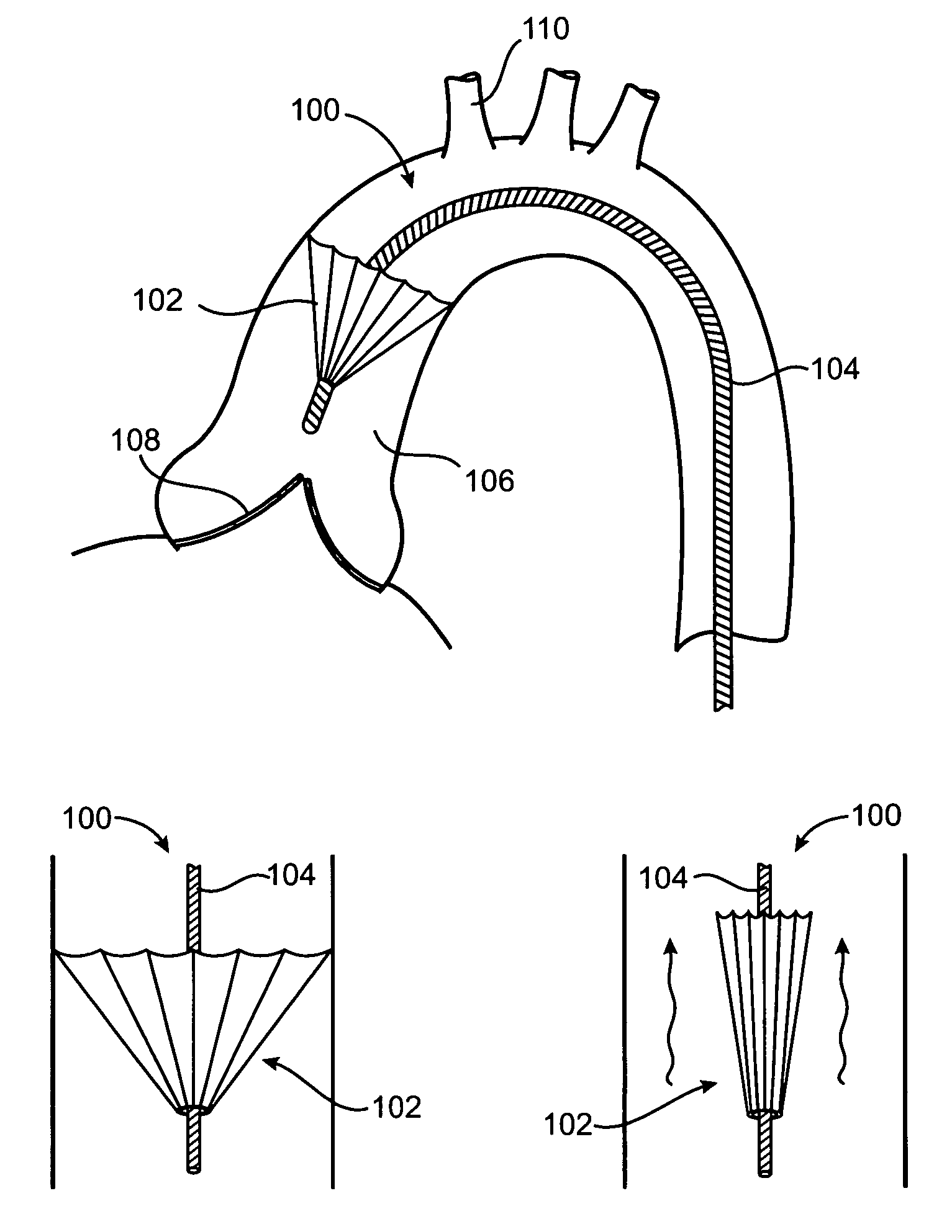
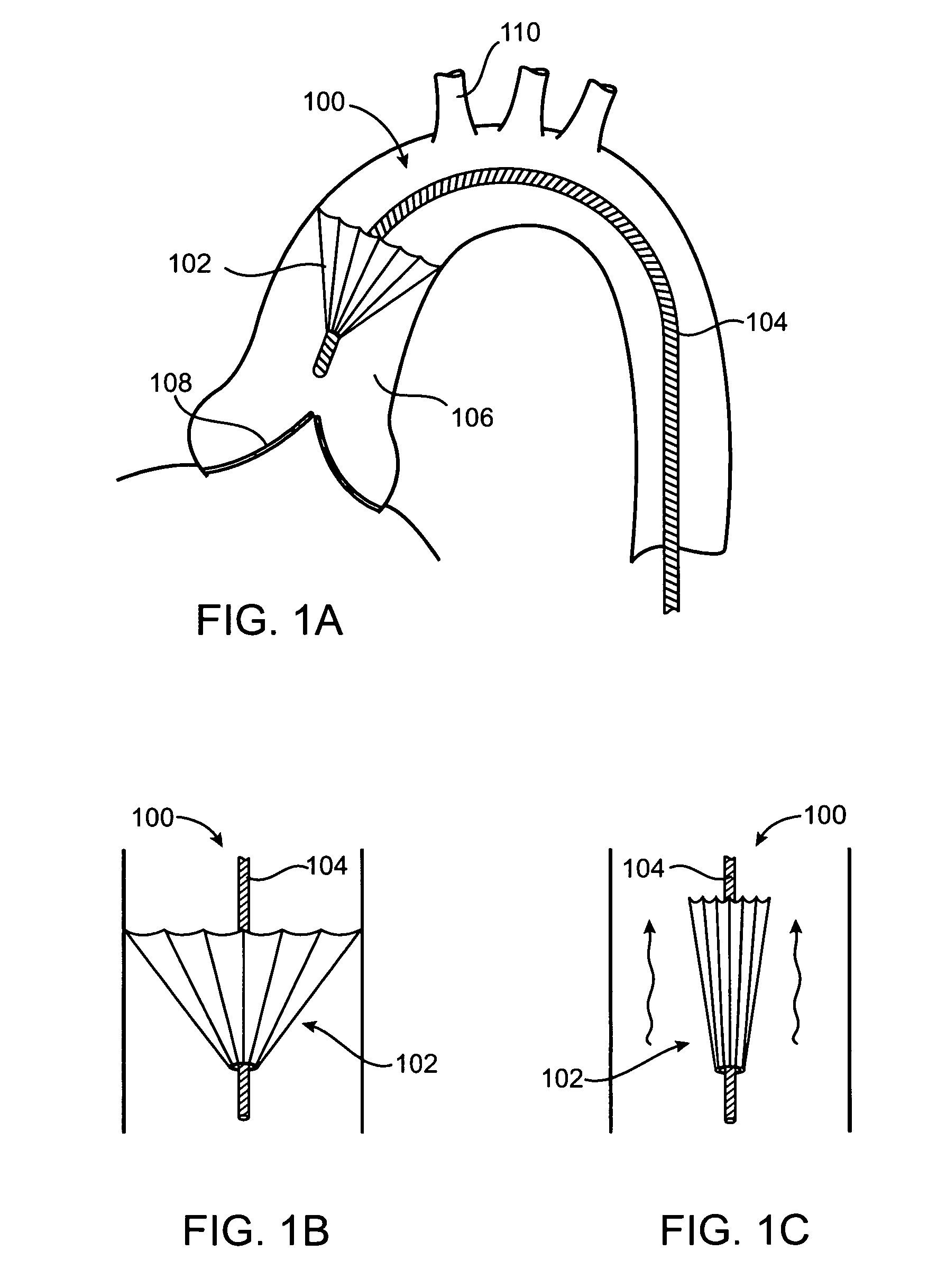
[0029]FIGS. 1A–1C, in which like elements share like reference numbers, shows a percutaneously delivered temporary valve system. FIG. 1A shows the temporary valve disposed in the ascending aorta, and FIGS. 1B & 1C show the temporary valve during diastole and systole, respectively. In one embodiment, the

[0030]Referring to FIG. 1A, the temporary valve system 100 comprises a temporary valve 102 connected to an elongate element 104. In the example shown, the temporary valve 102 is located in the ascending aorta 106 between the aortic valve 108 and the brachiocephalic artery 110. FIG. 1B shows the temporary valve 102 in the open position seating against the aortic wall to block retrograde blood flow during diastole. FIG. 1C shows the temporary valve 102 in the closed position at a reduced diameter to allow anterograde blood flow during systole. The temporary valve 102 alternates passively between the open and closed positions in response to the differential pressure across the valve. In ...


PUM


Abstract

The percutaneously delivered temporary valve assembly of the present invention, and method of using the same, provides an elongate element and a temporary valve disposed on the elongate element. The temporary valve can comprise struts and a membrane attached to the struts. The elongate element can include at least one lumen. The percutaneously delivered temporary valve assembly can be used to replace an aortic valve by locating a temporary valve in a patient's ascending aorta; deploying the temporary valve; removing the native aortic valve past the temporary valve; implanting the prosthetic aortic valve past the temporary valve; collapsing the temporary valve; and removing the temporary valve from the patient. The temporary valve can be sized to the patient and can be left in place while the prosthetic aortic valve heals in.

Description

RELATED APPLICATION[0001]This application claims priority to U.S. Provisional Application No. 60 / 466,938, “Percutaneously Delivered Temporary Valve” to Jeffrey W. Allen, et al., filed Apr. 30, 2003, the entirety of which is incorporated by reference.TECHNICAL FIELD[0002]The technical field of this disclosure is medical devices, particularly, a percutaneously delivered temporary valve assembly and method of using the same.BACKGROUND OF THE INVENTION[0003]Heart valves, such as the aortic valve, are sometimes damaged by diseases or by aging which can cause problems with the proper function of the valve. Heart valve disease generally takes one of two forms: stenosis, in which a valve does not open completely or the opening is too small, resulting in restricted blood flow; or insufficiency, in which blood leaks retrograde across the valve that should be closed. Valve replacement may be required in severe cases to restore cardiac function. In common practice, replacement requires open-hea...

Claims


Application Information

Patent Timeline
Patent Type & Authority Patents(United States)
IPC IPC(8): A61F2/06A61F2/24
CPCA61F2/2412A61F2/2427A61F2250/0059
Inventor ALLEN, JEFFREY W.BRIN, DAVID S.COPPIN, CHRIS M.
Owner MEDTRONIC VASCULAR INC
Why Eureka
Try Eureka