Apparatus and method for enhancing productivity of natural gas wells

a technology of natural gas wells and productivity, applied in the direction of drilling casings, drilling pipes, survey, etc., can solve the problems of increasing the flow pressure of bottomholes, increasing the flow of gas wells producing from reservoirs with depleting formation pressure, and constant pressure drop, so as to prolong the production life of gas wells, reduce the pressure of bottomholes, and increase gas flows

Active Publication Date: 2006-01-31
OPTIMUM PROD TECH INC
View PDF19 Cites 21 Cited by
  • Summary
  • Abstract
  • Description
  • Claims
  • Application Information

AI Technical Summary

Benefits of technology

[0024]For the foregoing reasons, there is a need for improved methods and apparatus for extending the production life of gas wells subject or susceptible to liquid loading, by reducing bottomhole pressures so as to induce increased gas flows into the well, and by providing means for maintaining gas velocities in the well at or above the critical velocity in order to prevent accumulation of liquids in the wellbore. There is also a need for such improved methods and apparatus which involve the injection of a pressurized gas into the well, but without inducing excessive friction loading in the well. In addition, there is a need for methods and apparatus capable of carrying out these functions on a continuous rather than cyclic or intermittent basis. There is a further need for such methods and apparatus which do not entail the installation of valves, packers, compressors, or other appurtenances down the well, and without requiring more than one string of tubing inside the well casing. There is an even further need for such methods and apparatus which do not require a complex array of valves and associated piping at the wellhead. The present invention is directed to these needs.
[0025]In general terms, the present invention is a system for enhancing production of a gas well by maintaining a velocity-induced flow regime, thus providing for continuous removal of liquids from the well and preventing or mitigating liquid loading and friction loading of the well. In accordance with the invention, a supplementary pressurized gas may be injected into a first chamber of a gas well as necessary to keep the total upward gas flow rate in a second chamber of the well at or above a minimum flow rate needed to lift liquids within the upward gas flow. A cased well having a string of tubing may be considered as having two chambers, namely the bore of the tubing, and the annulus between the outer surface of the tubing and the casing. For present purposes, these two chambers will also be referred to as the injection chamber and the production chamber, depending on the function they serve in particular embodiments. As will be seen, the present invention may be practised with the injection and production chambers being the annulus and the tubing bore respectively, or vice versa.
[0026]The invention provides for a gas injection pipeline, for injecting the supplemental gas into a selected well chamber (i.e., the injection chamber), and further provides a throttling valve (also referred to as a “choke”) for controlling the rate of gas injection, and, more specifically, to maintain a gas injection rate sufficient to keep the total gas flow rate of gas flowing up the other well chamber (i.e., the production chamber) at or above a set point established with reference to a critical flow rate. Strictly speaking, the critical flow rate is a well-specific gas velocity above which liquids will not drop out of an upward flowing gas stream. However, the critical flow rate may also be expressed in terms of volumetric flow based on the critical gas velocity and the cross-sectional area of the production chamber.
[0027]In accordance with the present invention, the critical flow rate for a particular well may be determined using methods or formulae well known to those skilled in the art. A “set point” (i.e., minimum rate of total gas flow in the production chamber) is then selected, for purposes of controlling the operation of the choke. The set point may correspond to the critical flow rate, but more typically will correspond to a value higher than the critical flow rate, in order to provide a margin of safety. Once the well has been brought into production, an actual total gas flow rate in the production chamber is measured. If the measured total gas flow rate (without gas injection) is at or above the set point, the choke will remain closed, and no gas will be injected into the well. However, if the measured total gas flow rate is below the set point, the choke will be opened so that gas is injected into the injection chamber at a sufficient rate to raise the total gas flow rate in the production chamber to a level at or above the set point.
[0028]The measurement of the gas flow rate in the production chamber may be made using a flow meter of any suitable type. Alternatively, the measurement may be made empirically, in trial-and-error fashion, by selective manual adjustment of the choke.
[0029]The process of measuring the total flow rate and adjusting the choke may be carried out on a substantially continuous basis. Alternatively, it may be carried out intermittently, at selected time intervals, and a timer may be used for this purpose.

Problems solved by technology

However, as wells penetrate the reservoir and gas reserves are removed, the formation pressure drops continuously, inevitably to a level too low to induce gas velocities high enough to sustain stable flow.
Therefore, all flowing gas wells producing from reservoirs with depleting formation pressure eventually become unstable.
This accumulation of liquids results in increased bottomhole flowing pressures and reduced gas recoveries.
The injected gas entering the jet compressor thus is accelerated upward within the tubing, thereby creating a venturi effect that induces a reduction in bottomhole pressure and a consequent drawdown on the gas-bearing formation.
The prior art technologies described above have proven useful for extending the productive life of gas wells that might otherwise have been abandoned due to liquid loading, but they have a number of drawbacks and disadvantages.
If this jet compressor malfunctions, it must be retrieved from the tubing and then repaired or replaced, in either case resulting in expense and lost production.
Although the Reitz system does not employ specialized downhole devices or packers as in the Canfield system, it requires an additional tubing string (i.e., the macaroni tubing) running inside the production tubing, plus a one-way valve at the bottom of the production tubing.
Malfunction of the one-way valve will require removal and replacement, resulting in expense and lost production.
Further drawbacks of the Reitz apparatus include the requirement for a complex array of valves connecting the various well chambers to the compressor's suction and discharge manifolds, plus the need for a controller to manipulate the valves according to the system's various cycles.
The use of pumps to remove accumulated liquids from gas wells also has disadvantages, most particularly including the cost of providing, installing, and maintaining the pump equipment.
A conventional reciprocating pump requires a string of “sucker rods” virtually the full length of the well, and if a rod breakage occurs, the entire string may need to be removed for repair, with consequent expense and loss of gas production.
It might be intuitively thought that the effectiveness of such gas injection would increase with higher injection rates and pressures, but this is not necessarily true.
The flow of a gas inside a conduit, such as the tubing or annulus in a well, causes “friction loading” due to friction between the flowing gas and the inner surfaces of the conduit.
Flow-induced friction forces increase with the square of the gas velocity, so efforts to increase gas production from marginal wells by increasing gas injection pressures and velocities may actually be counterproductive and futile.
It is apparent that any prior attempts to enhance or restore gas production using only gas injection have not met with practical success, possibly because the disadvantageous effects of increased injection rates were not fully appreciated.

Method used


Image

  • Apparatus and method for enhancing productivity of natural gas wells
  • Apparatus and method for enhancing productivity of natural gas wells
  • Apparatus and method for enhancing productivity of natural gas wells

Examples


Embodiment Construction

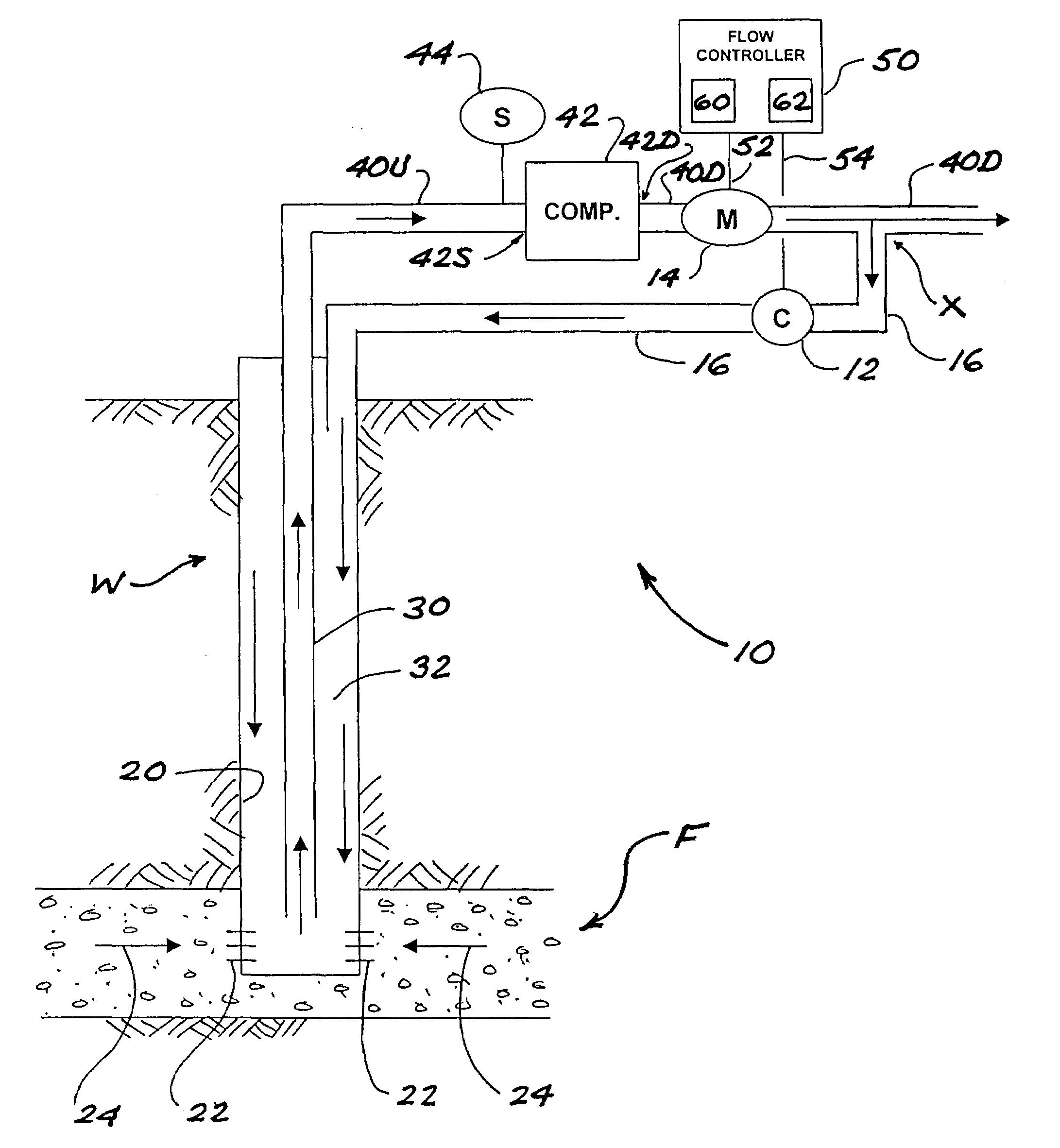
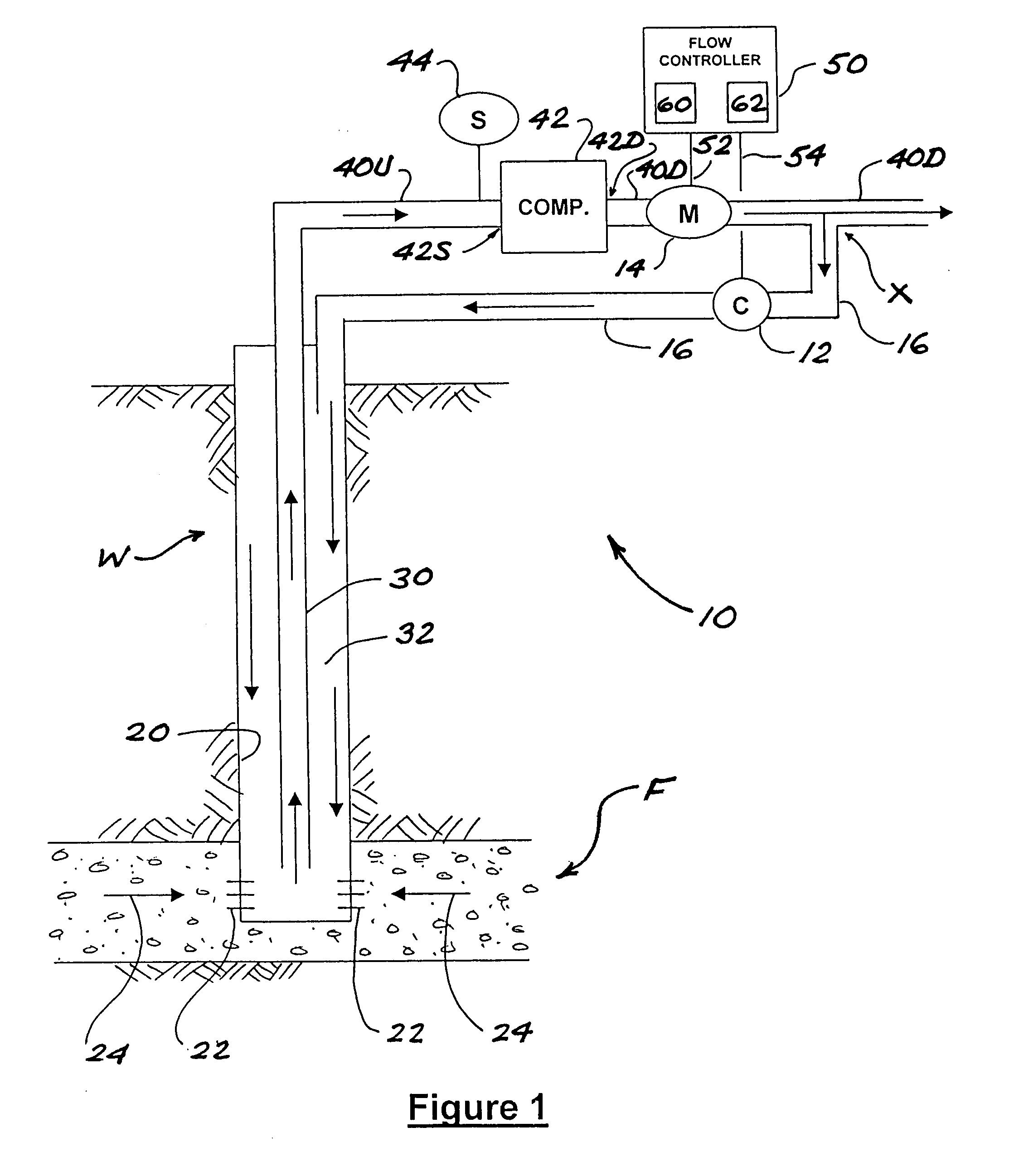
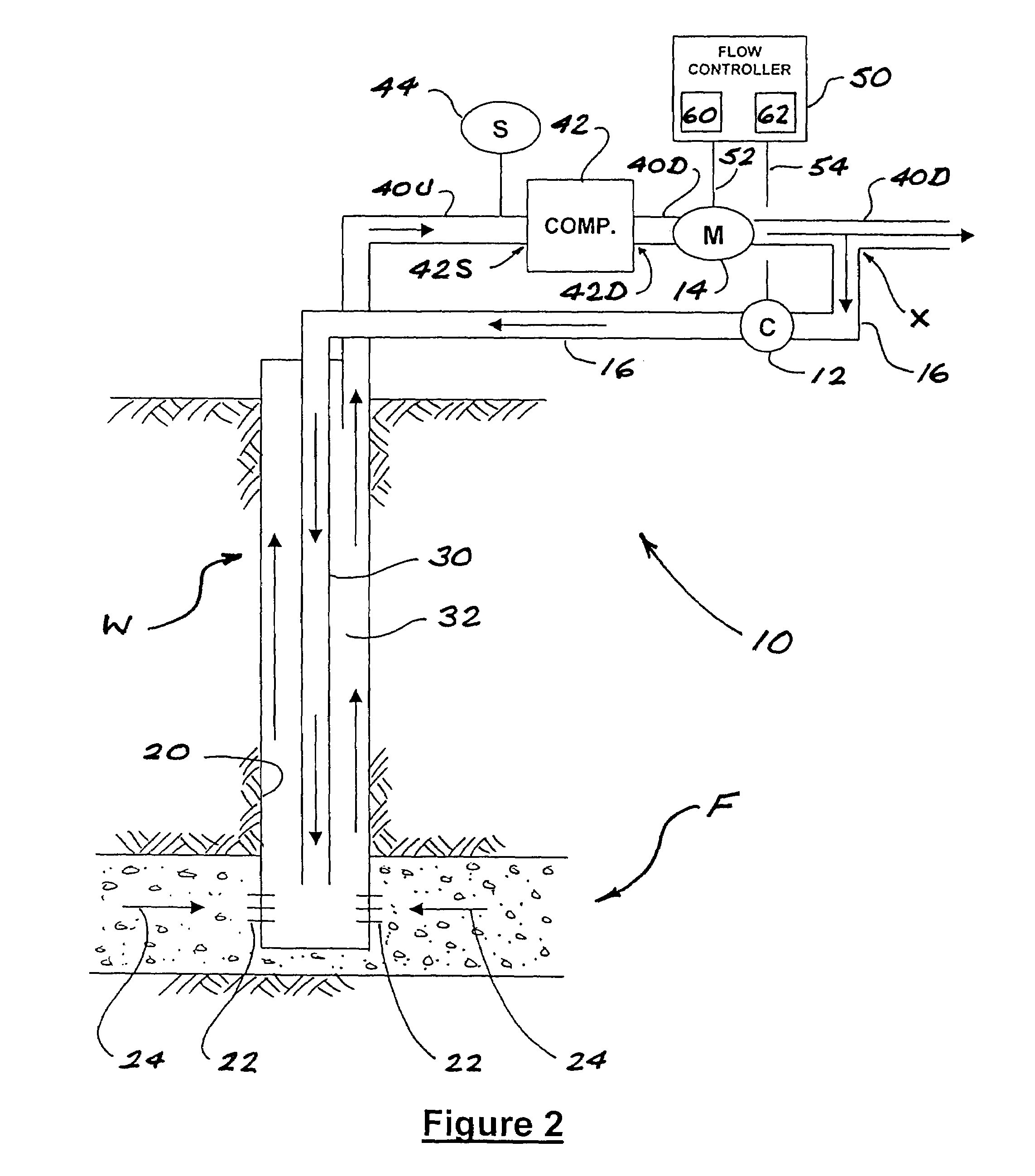
[0046]The basic elements of the present invention may be understood from reference to the Figures, wherein the apparatus of the invention is generally designated by reference numeral 10. A well W penetrates a subsurface formation F containing natural gas (typically along with water and crude oil in some proportions). The well W is lined with a casing 20 which has a number of perforations conceptually illustrated by short lines 22 within a production zone (generally corresponding to the portion of the well penetrating the formation F). As conceptually indicated by arrows 24, formation fluids including gas, oil, and water may flow into the well through the perforations 22. A string of tubing 30 extends inside the casing 20, terminating at a point within the production zone. The bottom end of the tubing 30 is open such that fluids in the wellbore may freely enter the tubing 30. An annulus 32 is formed between the tubing 30 and the casing 20.

[0047]As previously explained, the tubing 30 ...


PUM


Abstract

A natural gas production system prevents liquid accumulation in the wellbore and minimizes friction loading in the wellbore by maintaining production gas velocity above a critical minimum velocity. A pressurized gas is injected into the well to supplement the flow of production gas such that the velocity of the total gas flow up the well exceeds the critical velocity. A choke is fitted to the gas injection line, and total gas flows are measured by a flow meter. A flow controller compares the measured total gas flow rate against the critical flow rate, and determines a minimum gas injection rate required to maintain the total gas flow rate at or above the critical flow rate. The flow controller then adjusts the choke to achieve the desired gas injection rate. The injection gas may be recirculated production gas from the well, or a gas from a separate source.

Description

FIELD OF THE INVENTION[0001]The present invention relates to apparatus and methods of enhancing productivity in natural gas wells, and particularly in gas wells susceptible to liquid loading.BACKGROUND OF THE INVENTION[0002]Natural gas is commonly found in subsurface geological formations such as deposits of granular material (e.g., sand or gravel) or porous rock. Production of natural gas from these types of formations typically involves drilling a well a desired depth into the formation, installing a casing in the wellbore (to keep the well bore from sloughing and collapsing), perforating the casing in the production zone (i.e., the portion of the well that penetrates the gas-bearing formation) so that gas can flow into the casing, and installing a string of tubing inside the casing down to the production zone. Gas can then be made to flow up to the surface through a production chamber, which may be either the tubing or the annulus between the tubing and the casing.[0003]Formation...

Claims


Application Information

Patent Timeline
Patent Type & Authority Patents(United States)
IPC IPC(8): E21B47/00E21B43/12
CPCE21B43/122E21B43/12
Inventor WILDE, GLENN
Owner OPTIMUM PROD TECH INC
Why Eureka
Try Eureka