Near infrared ray shielding film

a screening film and infrared shielding technology, applied in the direction of spectral modifiers, synthetic resin layered products, textiles and paper, etc., can solve the problems of reducing the handling properties reducing the handling properties in processing or assembly steps, and reducing the bonding force of pressure sensitive adhesive layers. , to achieve the effect of preventing the malfunction of peripheral equipment, excellent handling properties, and high visible light transmission

Inactive Publication Date: 2006-01-31
TEIJIN LTD
View PDF21 Cites 34 Cited by
  • Summary
  • Abstract
  • Description
  • Claims
  • Application Information

AI Technical Summary

Benefits of technology

[0011]It is an object of the present invention to provide a near infrared screening film which is inexpensive, has excellent handling properties, high visible light transmission and the function of preventing the malfunction of peripheral equipment caused by near infrared rays radiated from the screen of a plasma display and can be suitably used in the front panel of a plasma display.
[0012]It is another object of the present invention to provide a near infrared screening film which is inexpensive, has excellent handling properties, high light transmission and the function of preventing the malfunction of peripheral equipment caused by near infrared rays radiated from the screen of a plasma display panel and can be suitably used in the front panel of a luminescent panel display, particularly a plasma display when it is assembled with an electromagnetic shielding thin film laminated film and a laminated film comprising the same.

Problems solved by technology

It is apprehended that this near infrared radiation may cause a problem such as the malfunction of peripheral equipment.
When the layer is thicker than 40 μm, it does not function as a self-adhesive and rather reduces handling properties in a processing or assembly step.
However, this reduces the bonding force of the pressure sensitive adhesive layer and handling properties.
When an expensive near infrared light absorber is to be contained in the pressure sensitive adhesive layer, it is dissolved in a solvent and the resulting solution is applied with a roll coater or gravure coater, whereby a great loss is produced by the control of film thickness and productivity, thereby significantly boosting cost.
In this method, since a bonding function is not required of the screening layer, a problem such as a reduction in adhesion does not occur unlike the pressure sensitive adhesive layer but the total thickness of layers becomes large and it is extremely difficult to control the thickness of each layer.
However, the filter still has disadvantages such as increases in film thickness and the number of steps resulted by the formation of the metal reflection layer, thereby boosting cost.

Method used


Image

  • Near infrared ray shielding film
  • Near infrared ray shielding film
  • Near infrared ray shielding film

Examples


example 1

[0202]Molten polyethylene terephthalate (PET, [η]=0.65) containing 0.05 wt % of the EX814K near infrared light absorber of Nippon Shokubai Co., Ltd., 0.05 wt % of the EX812K near infrared light absorber of Nippon Shokubai Co., Ltd. and 0.007 wt % of porous silica having an average particle diameter of 1.7 μm was extruded from a die and cooled on a cooling drum by a commonly used method to obtain an unstretched film. This unstretched film was stretched to 3.5 times in a longitudinal direction at 90° C. Thereafter, an aqueous solution containing 8% of the following coating composition was uniformly applied to both sides of the stretched film with a roll coater, and then the resulting laminate was stretched to 3.8 times in a transverse direction at 120° C. while it was dried at 95° C. and heat set at 230° C. to obtain a near infrared screening film having a thickness of 188 μm. The thickness of the adhesive layer was 0.15 μm. The evaluation results of the obtained film are shown in Tab...

examples 2 and 3

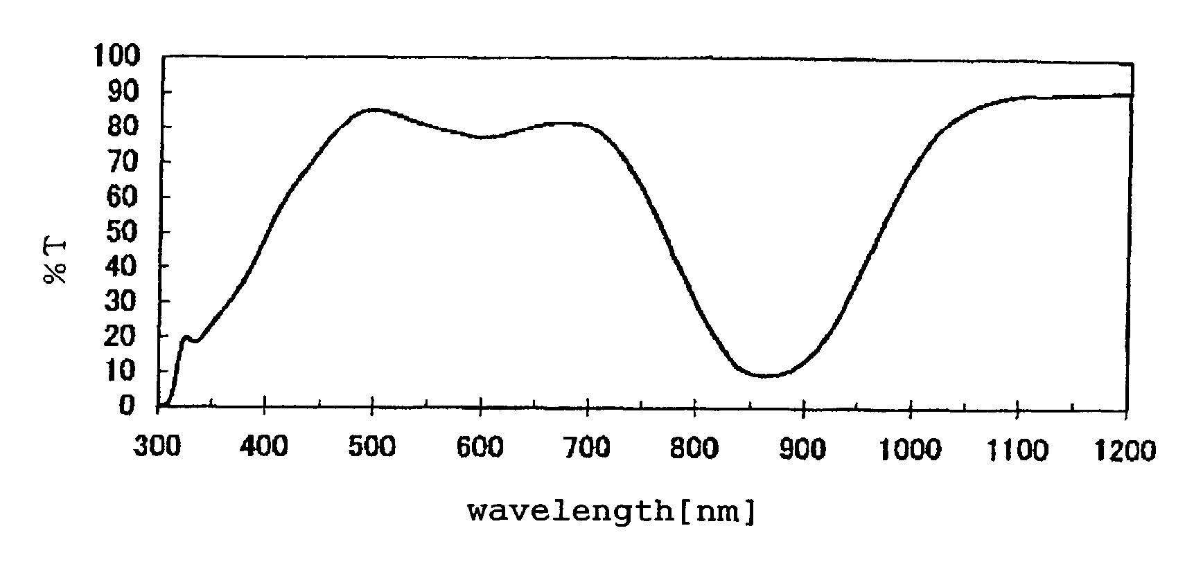
[0204]The procedure of Example 1 was repeated except that the near infrared light absorber was changed as shown in Table 1. The evaluation results of the obtained films are shown in Table 1. The transmittance of the film used in Example 2 is shown in FIG. 1.

example 4

[0205]Molten polyethylene-2,6-naphthalene dicarboxylate (PEN, [η]=0.65) containing 0.05 wt % of the EX814K near infrared light absorber of Nippon Shokubai Co., Ltd., 0.05 wt % of the EX812K near infrared light absorber of Nippon Shokubai Co., Ltd. and 0.007 wt % of porous silica having an average particle diameter of 1.7 μm was extruded from a die and cooled on a cooling drum by a commonly used method to obtain an unstretched film. This unstretched film was stretched to 3.5 times in a longitudinal direction at 130° C. Thereafter, an aqueous solution containing 8% of the following coating composition was uniformly applied to both sides of the stretched film with a roll coater, and then the resulting laminate was stretched to 3.8 times in a transverse direction at 120° C. while it was dried at 145° C. and heat set at 230° C. to obtain a near infrared screening film having a thickness of 188 μm. The thickness of the adhesive coating film was 0.15 μm. The evaluation results of the obtai...


PUM

PropertyMeasurementUnit
transmittanceaaaaaaaaaa
temperatureaaaaaaaaaa

Abstract

A near infrared screening film which consists of a biaxially oriented film made from a polyester containing a near infrared light absorber having a weight reduction start temperature of at least 280° C. and which has a haze value of 5% or less and a total transmittance for visible lights having a wavelength of 400 to 650 nm of 40% or more and which is exemplified by having optical properties at visible and near infrared ranges which satisfy the following expressions (1) to (4):1<T(850)<20  (1)1<T(950)<20  (2)−10<T(620)−T(540)<10  (3)−10<T(450)−T(540)<10  (4)wherein T(450), T(540), T(620), T(850) and T(950) are light transmittances at wavelengths of 450 nm, 540 nm, 620 nm, 850 nm and 950 nm, respectively.This film is inexpensive, has high handling ease, a high visible light transmittance and the function of preventing the malfunction of peripheral equipment caused by near infrared lights from the screen of a plasma display, for example, and can be suitably used in the front panel of the plasma display.

Description

FIELD OF THE INVENTION[0001]The present invention relates to a near infrared screening film and a laminated film comprising the same. More specifically, it relates to a near infrared screening film which is inexpensive, has excellent handling properties, high visible light transmission and excellent screening properties for near infrared rays having a wavelength of 820 to 980 nm and can be suitably used in the image display panel of a plasma display or the like, and to a laminated film comprising the same.DESCRIPTION OF THE PRIOR ART[0002]In the field of visual equipment typified by color TVs, the implementation of TVs of luminescent panel system using a plasma display or the like, non-luminescent panel system using a liquid crystal display or the like and rear projection system using a built-in image projector is now under way in addition to conventional direct-view TVs using a CRT to meet market demand for a large screen and a high-definition image.[0003]However, in the plasma dis...

Claims


Application Information

Patent Timeline
Patent Type & Authority Patents(United States)
IPC IPC(8): B32B7/12H04N5/65B32B27/06C08J5/18G02B1/10G02B5/20G02B5/22H01J5/08H01J17/16
CPCC08J5/18G02B1/10G02B5/208G02B5/22H01J11/44H01J5/08C08J2367/02Y10T428/28H01J2211/448Y10T428/2843Y10T428/2848Y10T428/24835Y10T428/249953Y10T428/31797Y10T428/31794G02B1/115
Inventor OYA, TARO
Owner TEIJIN LTD
Why Eureka
Try Eureka