
Method and apparatus for analyzing a substance using MSn analysis

Inactive Publication Date: 2006-01-31
DH TECH DEVMENT PTE +2
View PDF5 Cites 15 Cited by
  • Summary
  • Abstract
  • Description
  • Claims
  • Application Information

AI Technical Summary

Benefits of technology

[0032]Preferably, the apparatus additionally includes a detector for detecting fragment ions exiting the collision cell, a switch connected to the detector, two data storage devices connected to the switch, and a connection between the modulation control un

Problems solved by technology

A problem with this conventional arrangement is that the two mass resolving quadrupoles are required to operate in the high vacuum region (less than 10−5 torr), while the intermediate collision cell operates at a pressure up to several millitorr.
Ion losses occur at each stage, however, so that sensitivity decreases as the number of steps increases.
The first technique taught above is complex, and requires a number of separate quadrupoles or the like, and the ability to move the ions sequentially through the different quadrupole sections.
The technique taught in the Finnigan patent is complex and requires a number of steps.
While all of the above methods can be used to obtain MS3 spectra (or higher order), they all suffer from some limitations or drawbacks.
The method described in Whitehouse et al to achieve MS3 is complex, and reduces the duty cycle for the overall process (as described by the inventors of the '259 patent) to 33% for MS3.
It is desirable to provide this in a single device, since movement of ions from one device to another inevitably leads to some losses.
Similarly, the techniques of the Finnigan patent works effectively with pulse ion sources, but inefficiently with continuous ion flow, for instance from an electrospray ion source.

Method used


Image

  • Method and apparatus for analyzing a substance using MSn analysis
  • Method and apparatus for analyzing a substance using MSn analysis
  • Method and apparatus for analyzing a substance using MSn analysis

Examples


Embodiment Construction

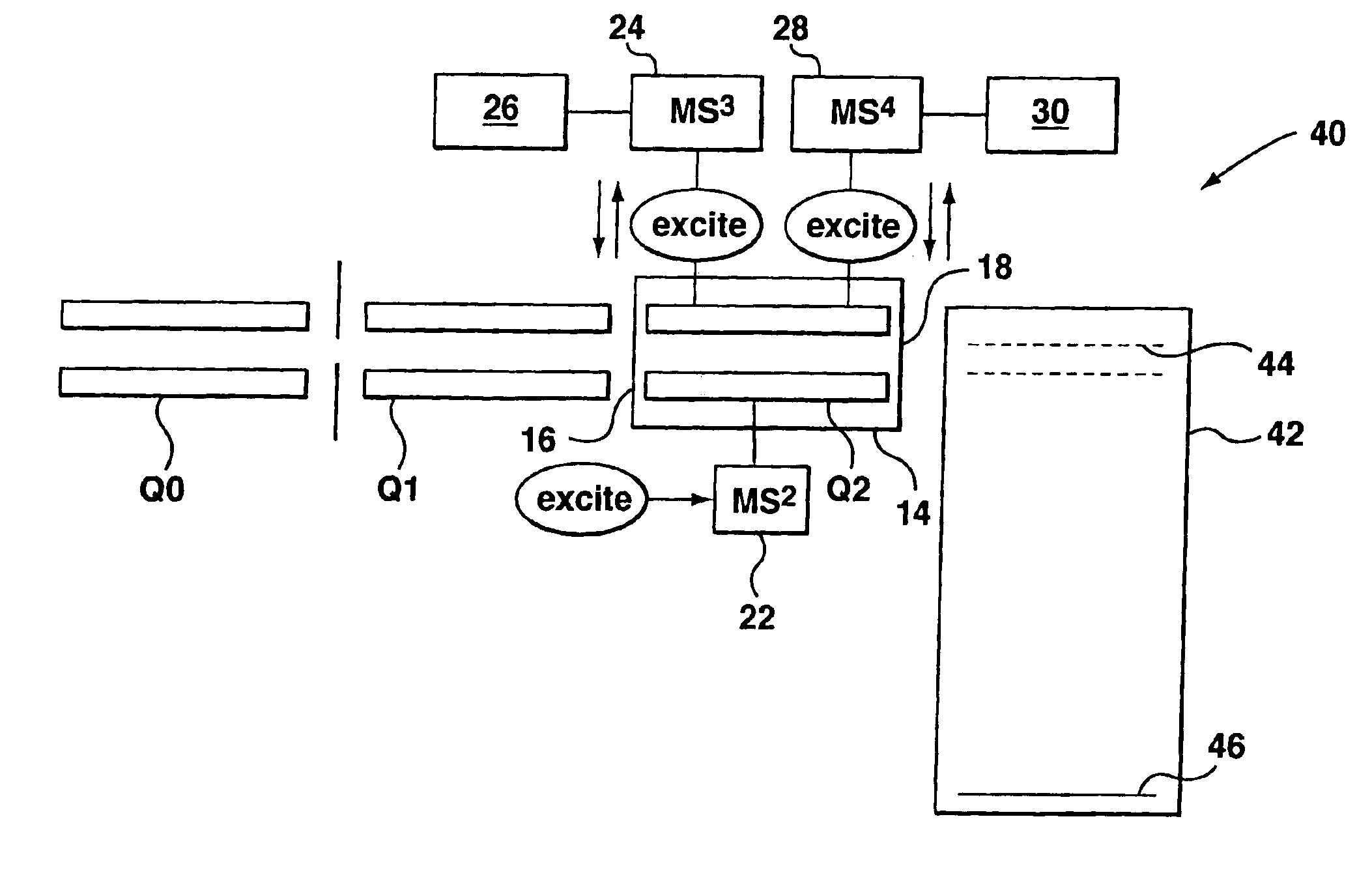
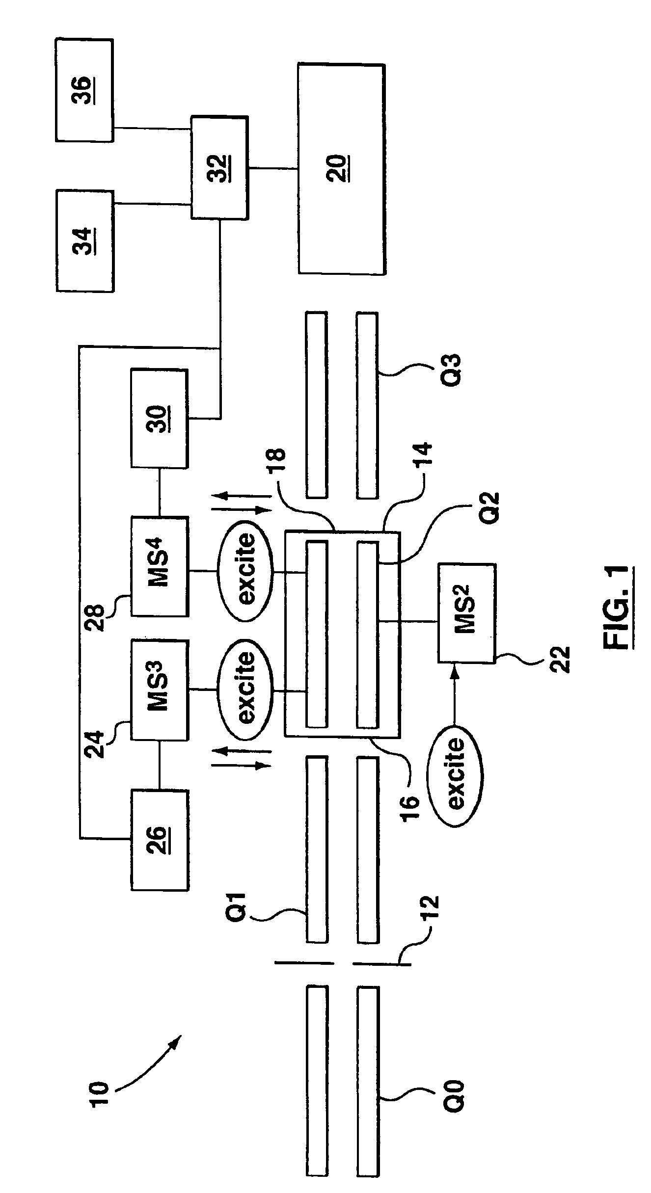
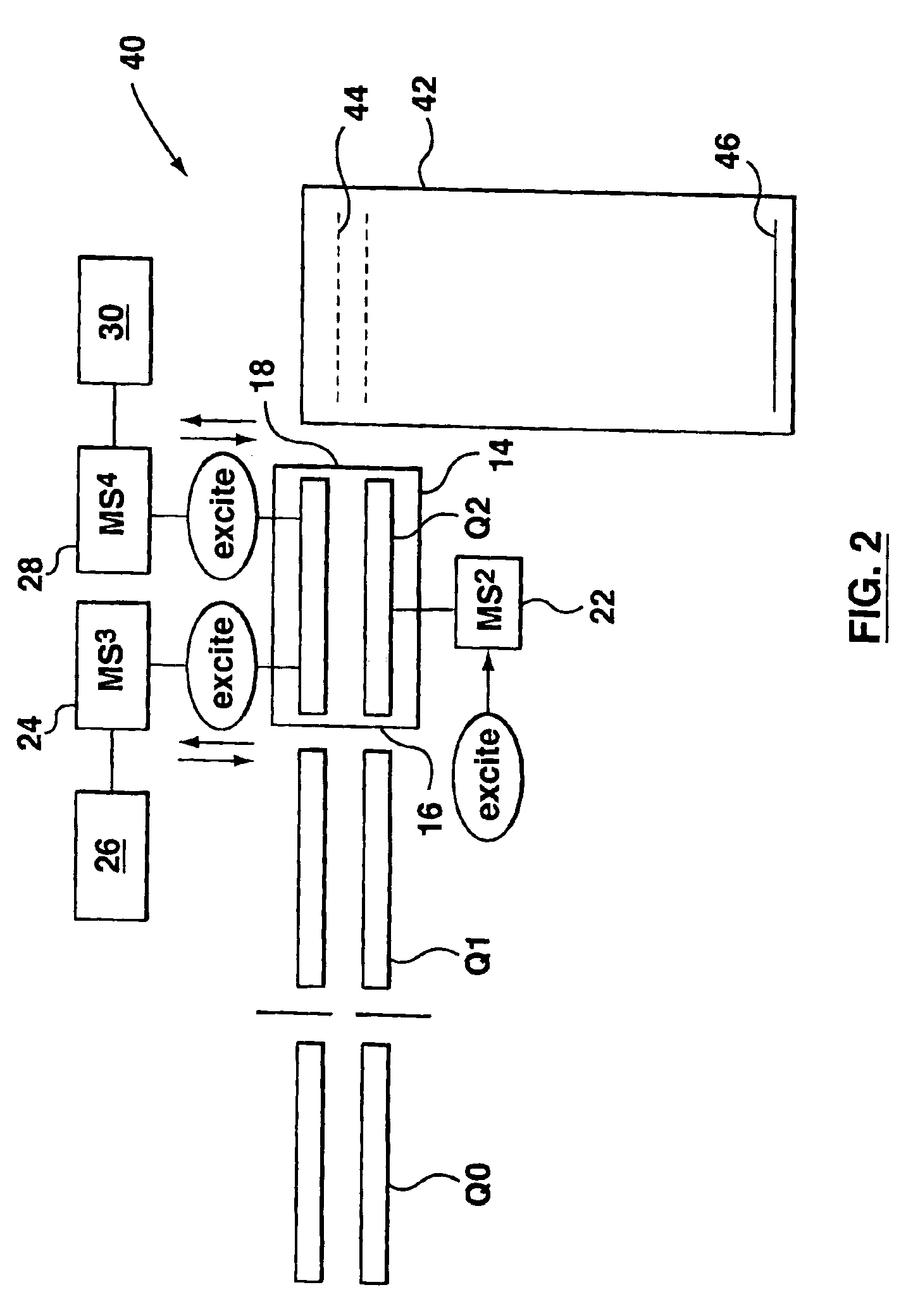
[0043]A description is first given of the apparatus in FIGS. 1 and 2. The two apparatus are largely similar, except for the final mass analysis stage. FIG. 1 shows a variant with a quadrupole rod set and detector as the final mass analysis stage, while this is effected by a time-of-flight section in FIG. 2.

[0044]Referring first to FIG. 1, the first variant of the apparatus is indicated at 10. In known manner, the apparatus 10 includes a first quadrupole rod set generally indicated as Q0. Q0 is intended to collimate and reduce the energy of ions received from an electrospray source or the like. In known manner, upstream of Q0, there would be an ion inlet, skimmers, intermediate pressure stages and the like, all intended to remove gas and reduce pressure down to that required for mass analysis (these elements and associated pumps are not shown). Q0 collimates the ion beam and further serves to reduce gas pressure.

[0045]Ions from Q0 pass through an interquad aperture 12 into a quadrupo...


PUM


Abstract

A method of and apparatus for analyzing a substance takes a stream of ions in said substance and supplies the ions to a collision cell including a quadrupole rod set for guiding the ions and a buffer gas. An RF voltage is applied to the quadrupole rod set to guide ions. An additional alternating current signal is applied to the quadrupole rod set at a frequency selected to cause resonance excitation of the secular frequency of a desired ion, whereby said desired ions are excited and undergo collision with the buffer gas causing fragmentation. The alternating current signal is then modulated, whereby periods in which said alternating current signal is applied alternate with periods in which said alternating signal is not applied. The ion spectrum after fragmentation is collected to generate one set of data for one spectrum, representative of the ion spectrum when the alternating current signal is applied, and another set of data for another spectrum, representative of the ion spectrum when the alternating current signal is not applied. These two spectra can then be subtracted.

Description

FIELD OF THE INVENTION[0001]This invention relates mass spectrometers, and more particularly is concerned with collision-induced dissociation (CID) in a tandem mass spectrometer. The invention is particularly intended to enable multiple stages of fragmentation, and hence mass analysis or spectroscopy, to be effected in a collision cell.BACKGROUND OF THE INVENTION[0002]Radio frequency (RF) only multipole spectrometers, more particularly quadrupole spectrometers, are widely applied in mass spectrometry and nuclear physics, due to their ability to transport ions with minimal losses. During such transportation of the ions, the initial ion positions and velocities change, but the total phase space volume occupied by the ion beam remains constant (see Dawson, P. H., “Quadrupole Mass Spectrometry and its Applications,” Elsevier Scientific Publishing Co., New York, 1976). However, if a buffer gas is introduced into the ion guide, a dissipative process occurs, due to ion molecule collisions,...

Claims


Application Information

Patent Timeline
IPC IPC(8): H01J49/00H01J49/42H01J49/04H01J49/26H01J49/36
CPCH01J49/063H01J49/0063
Inventor COUSINS, LISATHOMSON, BRUCE
Owner DH TECH DEVMENT PTE
Learn More