Low cost broad range loudspeaker and system

a loudspeaker and low-cost technology, applied in the direction of deaf-aid sets, electrical transducers, transducer details, etc., can solve the problems of limiting the frequency response and sound quality achievable, imposing severe limitations on the effectiveness of the technique of drive power compensation, and limiting the effect of driving efficiency

Inactive Publication Date: 2006-01-31
NUTTER MCCLENNEN & FISH
View PDF66 Cites 33 Cited by
  • Summary
  • Abstract
  • Description
  • Claims
  • Application Information

AI Technical Summary

Benefits of technology

[0019]Loudspeaker magnetic motors as provided by the invention feature several advantages over the prior art. They provide a low cost, practical method for maximizing the available engine strength B L2/r in a small speaker with a rare earth magnet motor. This leads to an improved cost performance ratio b

Problems solved by technology

However, the physics of sound generation, as well as the resistance or inductance of the coil tend to limit the frequency response and quality of sound achievable as the speaker size gets smaller.
However, when one adds the constraint of using a low operating

Method used


Image

  • Low cost broad range loudspeaker and system
  • Low cost broad range loudspeaker and system
  • Low cost broad range loudspeaker and system

Examples


embodiment 1

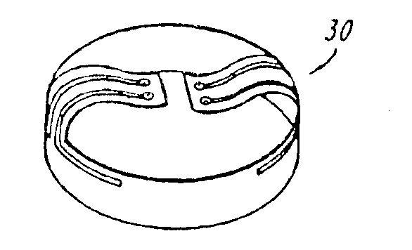
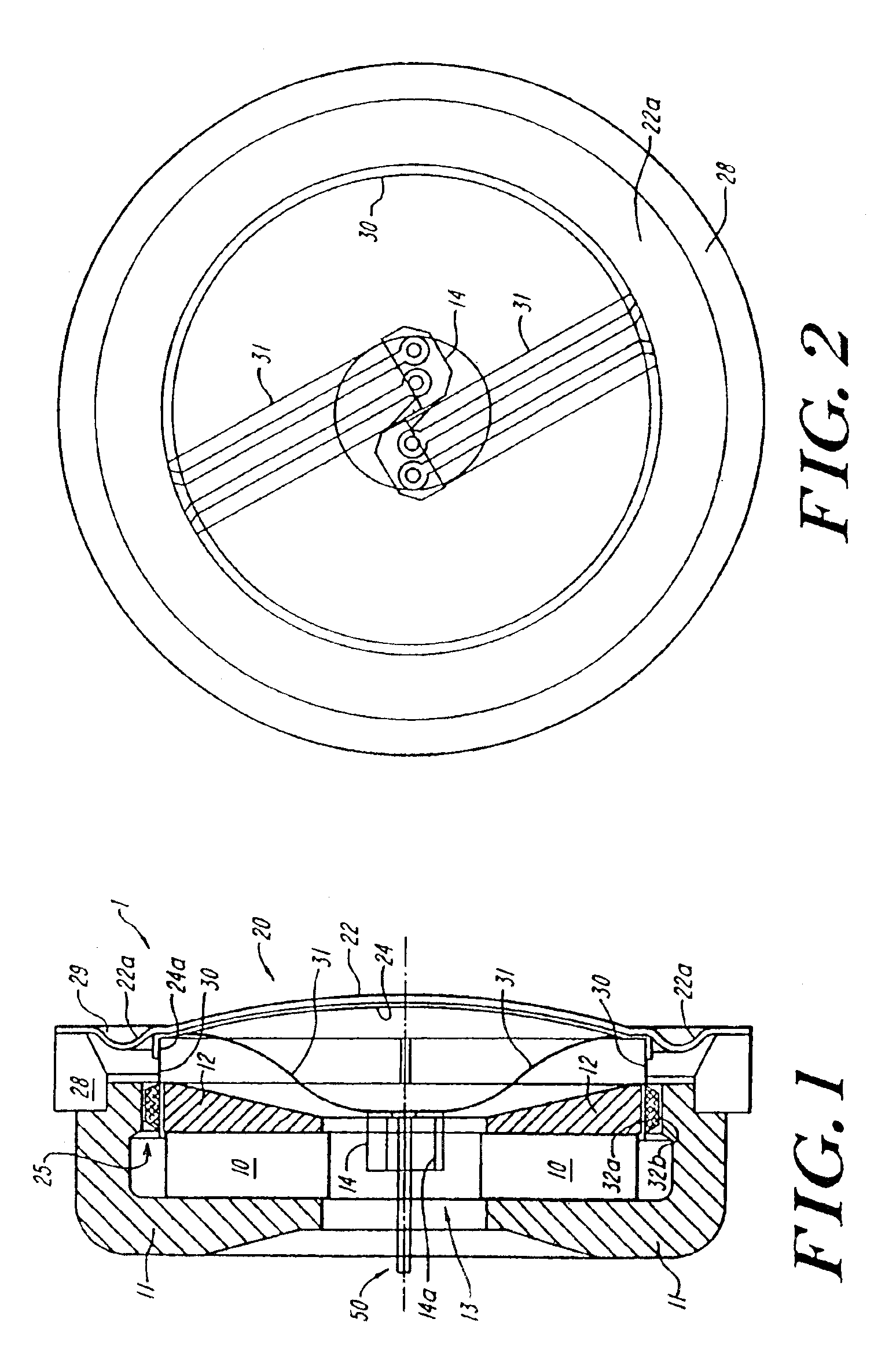
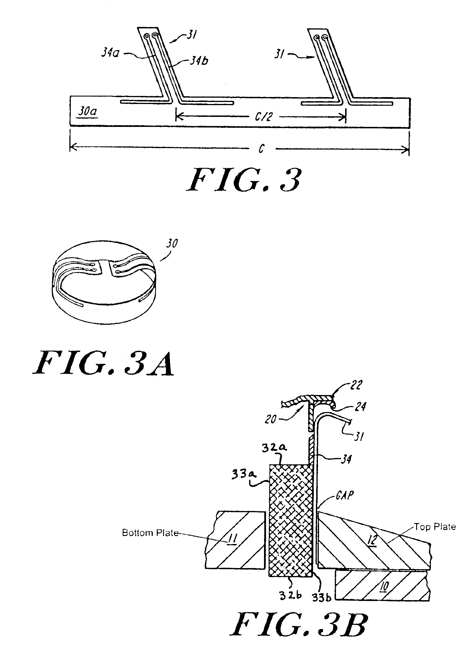
[0035]In the illustrated embodiment 1, the diaphragm 20 is preferably dished or domed outwardly, providing a shape of enhanced stiffness and resistance to flexural mode excitation. This shape also acts effectively as a point-source acoustic radiator, allowing enhanced phase control of the sound transduced thereby. The upper pole piece 12 is tapered or angled inwardly back toward the center, so that it has relatively little mass in the central region and thus more efficiently concentrates flux in the gap. Both of these physical contours also provide spatial clearance behind the diaphragm 20 to permit both deflection of the diaphragm and enhanced clearance for the lead in connectors 31 to flex and move with the diaphragm without contacting surrounding structures. The lead in connector 31 may be soldered to a snap-in terminal block 14, which may be formed, for example, as a female jack connector, to which drive power from an external amplifier is supplied along the input drive lines 50...

first embodiment

[0039]FIG. 4 illustrates another embodiment of a small, broad range speaker in accordance with the invention. Like components are numbered identically to those of FIG. 1. By way of scale, this embodiment has a total diameter of the lower pole piece equal to 31.6 millimeters, with a 26×0.04 mm stainless steel diaphragm of 5.5 square centimeter effective area. This construction specified a flat diaphragm, and rubber loading only in the perimeter and suspension band, with a total speaker height of 7.5 mm, a total weight of 22 grams, and a free air resonance of the suspended diaphragm of 180 Hz. Using a 7.5 gram magnet of Neodymium 40, a one-inch circular gap 2.5 mm high by 0.85 mm width, the speaker had a flux B in the gap of 1.1 Tesla, with a gap energy of 80 mWattsec. Two parallel copper wire windings 2.0 meters long carrying 7.5 watts provide effective drive force for a substantially linear response, with 20 dB drop-off points at 90 Hz and 22 kHz. In other embodiments, the system mo...


PUM


Abstract

A loudspeaker has a diaphragm with a voice coil disposed about its perimeter and extending in a gap into which the flux of an annular rare earth magnet is focused. An opening behind the diaphragm communicates through the speaker frame. The voice coil may have two or more windings that are connected in parallel, and may, e.g., be layered on top of one another, so that the impedance of the coil, as well as its depth in the front/back direction of motion, are low. The voice coil is preferably implemented using a polyamide form or bobbin, which has patterned lead-in conductors embedded therein to bring power to wire windings on the perimeter of the coil. The lead-in conductors extend to, or through, the central opening of a ring magnet, providing a robust ribbon input connection.

Description

REFERENCE TO RELATED APPLICATIONS[0001]This application is related to U.S. patent application Ser. No. 09 / 439,416, filed Nov. 13, 1999, which is hereby incorporated herein by reference in its entirety. This application is a continuation of U.S. Ser. No. 09 / 639,416, filed Aug. 14, 2000 now U.S. Pat. No. 6,654,476. This application claims the benefit of Provisional Application No. 60 / 148,863, filed Aug. 13, 1999.BACKGROUND OF THE INVENTION[0002]The invention relates to loudspeakers and to low-cost magnetic motors for use in loudspeakers. The invention has application, among other places, in portable consumer electronics, in cell phones, pagers, digital music players, and other apparatus where weight and size are factors. It has particular utility in applications that rely upon a main power source having a relatively low voltage, e.g., between about three to approximately twelve volts, and in further aspects provides compact full range systems.[0003]A large percentage of loudspeakers a...

Claims


Application Information

Patent Timeline
IPC IPC(8): H04R25/00H04R11/02
CPCH04R11/02
Inventor GUENTHER, GODEHARD A.
Owner NUTTER MCCLENNEN & FISH
Why Eureka
Try Eureka