On-chip variable oscillator method and apparatus

a variable oscillator and oscillator technology, applied in the direction of oscillator generator, logic circuit pulse generation, automatic control of pulses, etc., can solve the problems of not being able to directly produce the very high frequency required in some high performance circuitry, external clock generators tend to be expensive, and expensive clock generators generate high frequency clocks on the system board

Inactive Publication Date: 2006-02-07
HEWLETT PACKARD DEV CO LP
View PDF5 Cites 35 Cited by
  • Summary
  • Abstract
  • Description
  • Claims
  • Application Information

AI Technical Summary

Benefits of technology

[0008]In another embodiment of the present invention, a sample clock oscillator is added to the circuit creating an independent clock for analyzing the frequency of the ring oscillator. The independent sample clock runs at a greater frequency than the ring oscillator so the f

Problems solved by technology

Crystal controlled oscillators are generally useful for precisely creating a desired frequency, but cannot directly produce the very high frequencies required in some high performance circuitry.
As a result, external clock generators tend to be expensive.
Generally, expensive clock generators generate high frequency clocks on a system board and maintaining a clean clock signal at high frequencies is problematic.
To be accurate, yet flexible enough to g

Method used


Image

  • On-chip variable oscillator method and apparatus
  • On-chip variable oscillator method and apparatus
  • On-chip variable oscillator method and apparatus

Examples


Embodiment Construction

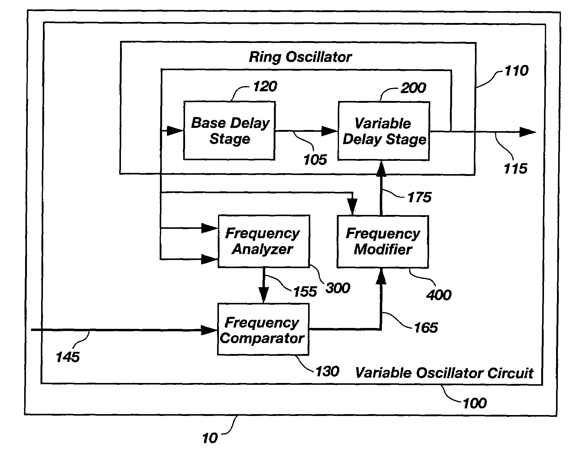
[0021]FIG. 1 illustrates a variable oscillator circuit 100 contained on a semiconductor device 10 in accordance with an embodiment of the present invention. The present embodiment generates a variable frequency-oscillating signal 115 from a ring oscillator 110. The ring oscillator 110 is comprised of a base delay stage 120 and a variable delay stage 200 connected in a ring. The ring is formed by connecting the output of the base delay stage 120 to a variable delay input 105 signal and connecting the variable frequency-oscillating signal 115 back to the input of the base delay stage 120. As long as the ring is configured to have an odd number of logical inversions, the ring oscillates. An oscillation frequency of the ring varies depending on the total delay through the base delay stage 120 and the variable delay stage 200. The maximum frequency for the variable frequency-oscillating signal 115 occurs when the minimum amount of delay is selected within the variable delay stage 200. Th...


PUM


Abstract

A method and apparatus for creating a variable frequency-oscillating signal on a semiconductor device. The frequency of a ring oscillator is varied by inserting or removing additional delay into the ring. The frequency of the oscillating signal is periodically compared to an encoded input signal indicating the desired frequency. The comparison result modifies the desired frequency by modifying the amount of delay in the ring oscillator. In an alternate reference clock is converted to an encoded representation of the input reference clock's current frequency. This resultant encoded representation is compared to the encoded representation of the variable frequency-oscillating signal to determine whether the delay in the ring oscillator should be modified so the frequency of the variable oscillating signal matches the frequency of the input reference clock.

Description

BACKGROUND OF THE INVENTION[0001]1. Field of the Invention[0002]The present invention relates to ring oscillator circuits for generating variable frequencies. More particularly, the present invention relates to ring oscillator circuits for test chips used for evaluation purposes wherein the oscillator frequency may be varied.[0003]2. Description of Related Art[0004]Oscillators are well known in the art and important in providing clock signals in digital logic circuits. Clock generation for semiconductor devices can take many forms including ring oscillators, crystal controlled oscillators, external clock devices, Phase Locked Loops (PLL) on a semiconductor device, Delay Locked Loops (DLL) on a semiconductor device, and various combinations of the above. Crystal controlled oscillators are generally useful for precisely creating a desired frequency, but cannot directly produce the very high frequencies required in some high performance circuitry. Similarly, external clock generators v...

Claims


Application Information

Patent Timeline
IPC IPC(8): H03B5/00
CPCH03L7/0995H03K3/0315
Inventor CULLER, JASON H.
Owner HEWLETT PACKARD DEV CO LP
Why Eureka
Try Eureka