System and method for remote quantitative detection of fluid leaks from a natural gas or oil pipeline

a pipeline and fluid leak technology, applied in the field of spectroscopic analysis, can solve the problems of inability to make a direct visual assessment of pipeline failures, failures in pipelines, and continuous inability of lasers to be tunable, and achieve the effect of reasonable wavelength conversion efficiency

Active Publication Date: 2006-02-07
HARRIS CORP
View PDF23 Cites 118 Cited by
  • Summary
  • Abstract
  • Description
  • Claims
  • Application Information

AI Technical Summary

Benefits of technology

[0014]The present invention has the following advantages: it utilizes a well-developed one-micron Diode Pumped Solid-State, Optical Parametric Oscillator and Optical Parametric Amplifier; it has reasonable wavelength conversion efficiency; it is capable of measuring multiple targets concentration pathlength as the surface cover type (background) changes; and it is continuously tunable.

Problems solved by technology

In detecting failures of gas and oil pipelines there is a particular problem, as the gas or oil pipeline is typically buried beneath ground level.
In such cases, it is difficult to make a direct visual assessment of any failures in the pipeline.
Typically, failures in pipelines are currently determined by having personnel walk the pipeline on a periodic and costly basis with some means to detect the trace emanating from the pipeline.
For oil or petroleum pipelines, release of certain volatile components can indicate the presence of a fluid leak, and thus constitute indirect evidence of a pipeline failure.
CO2 lasers are continuously not tunable and lack strong lines at wavelengths coincidental with acceptable methane and ethane lines.
He—Ne lasers are typically not tunable and not as efficient and reliable as solid-state lasers.
This system does not allow for real-time compensation for variability in the background target reflectivity and cannot measure multiple gas species nearly simultaneously, a critical requirement for scanning and remote sensing systems that detect pipeline leaks.
This system only discloses detection of methane and does not allow for real-time compensation for variability in the background target reflectivity.
The quartz crystals are easily damaged by high-energy laser pulses and complexity of this system is not conducive to use in the field, particularly in airborne remote sensing applications.
Also, the laser spectral width is too broad to resolve the absorption bands of many key gases.
This system does not conveniently allow for real-time compensation for variability in the background target reflectivity and simultaneous detection of other gases.
Furthermore, the single laser frequency is referenced to an external frequency meter and is, therefore, subject to drift that negatively affects the electronic components in the system.

Method used


Image

  • System and method for remote quantitative detection of fluid leaks from a natural gas or oil pipeline
  • System and method for remote quantitative detection of fluid leaks from a natural gas or oil pipeline
  • System and method for remote quantitative detection of fluid leaks from a natural gas or oil pipeline

Examples


Embodiment Construction

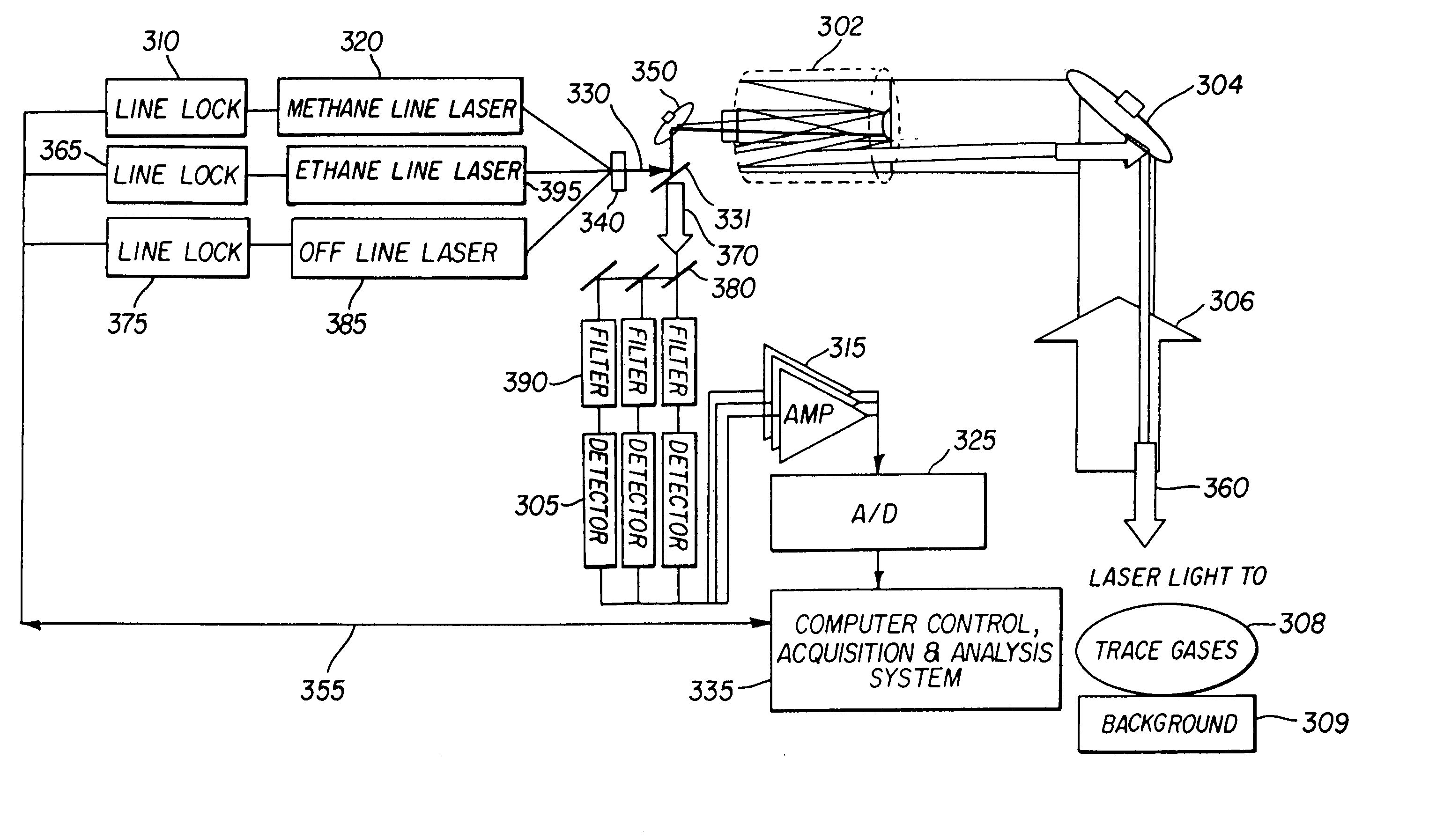
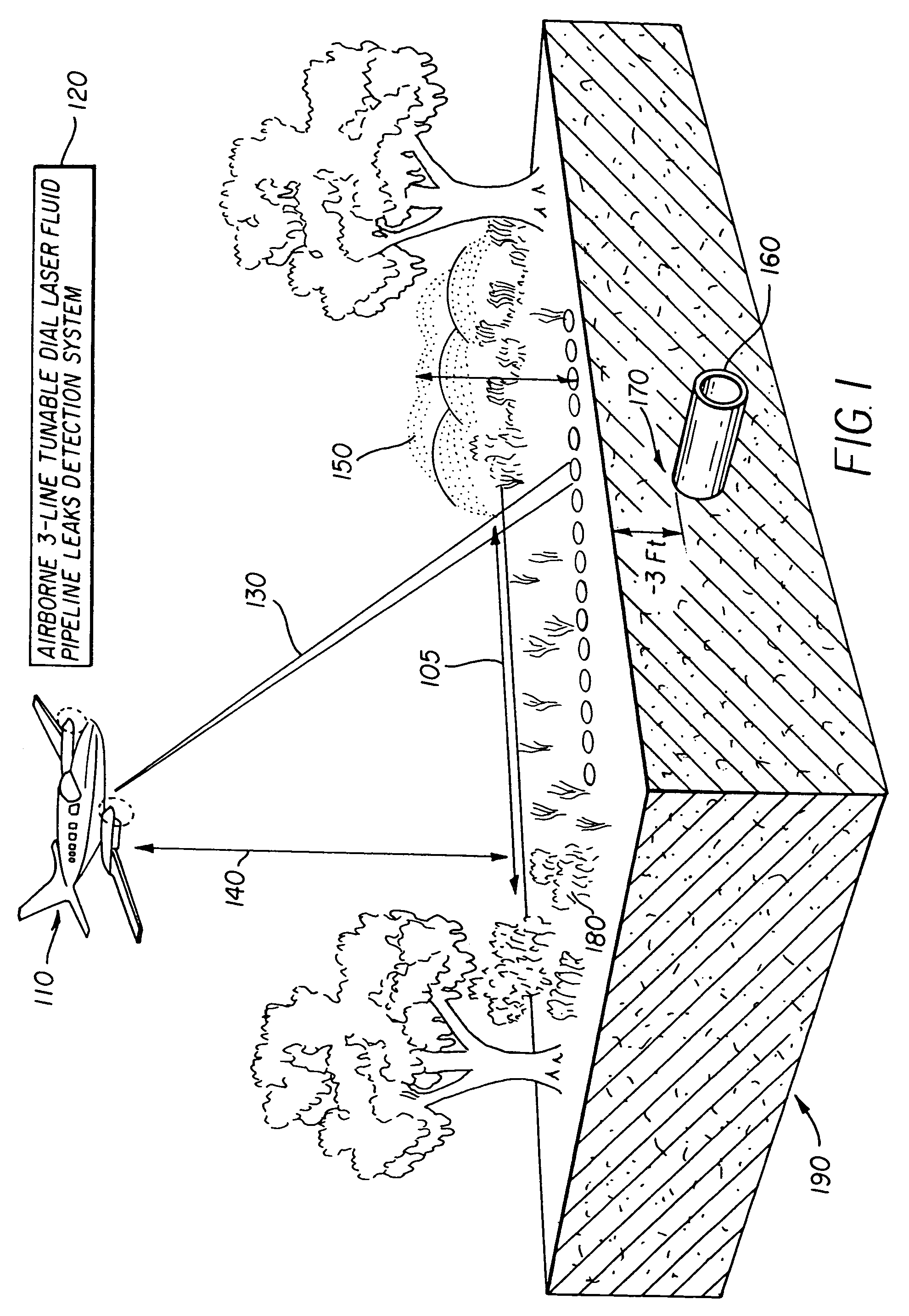
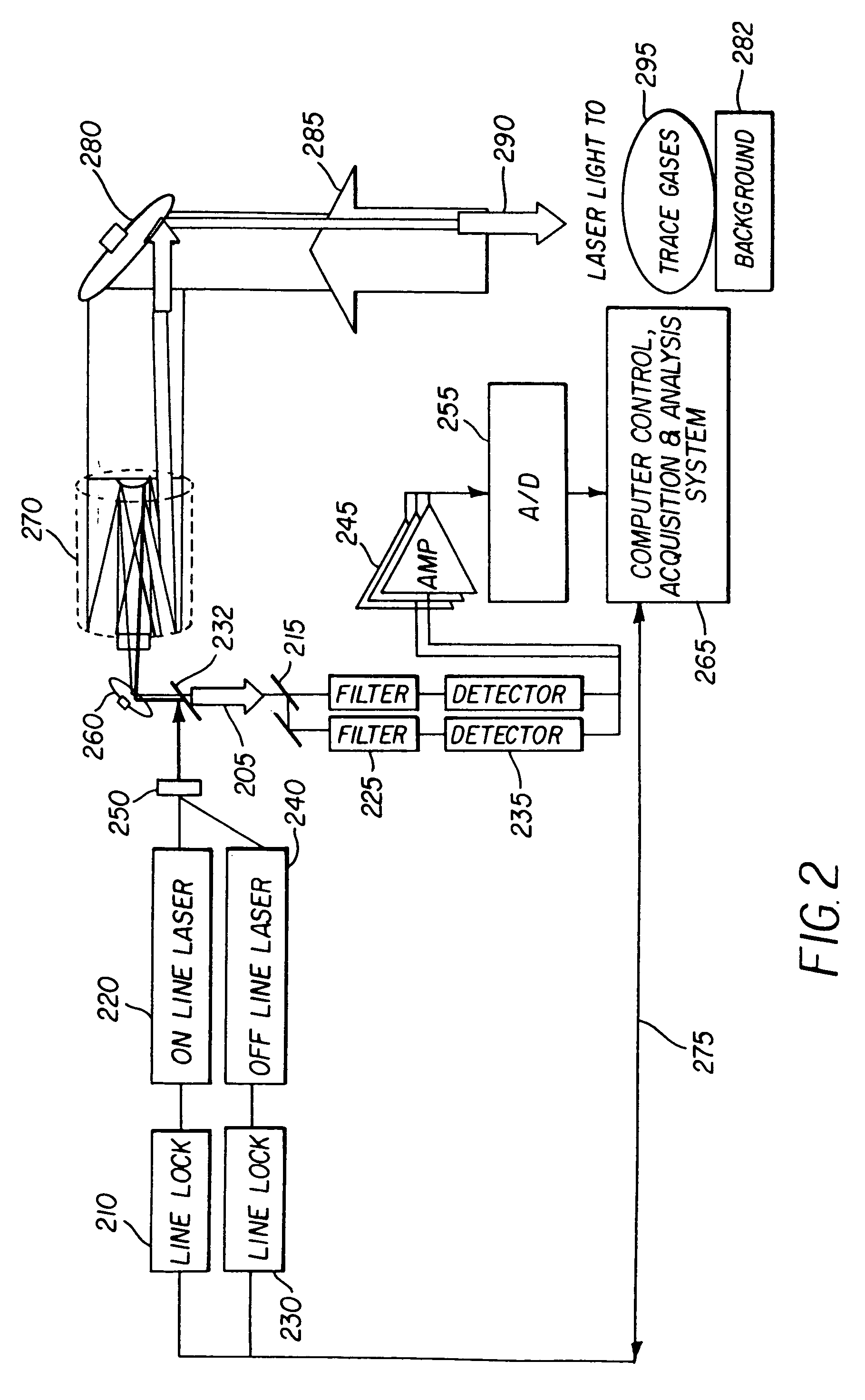
[0028]The present invention described herein addresses the measurement of gases associated with oil and gas leakages from pipelines. This invention relates to an oil and gas pipeline leak detection system and method of detecting gases in the atmosphere and more particularly, but not by way of limitation, to detecting pipeline leaks based upon differential absorption lidar (DIAL) sensing techniques operating in a mid-infrared 2 to 5 micrometers, spectral range. In general, the following fluids may be detected or explored: gas, volatile oil, light crude oil, heavy crude oil, and hazardous. The gas concentrations are mapped over an area and the maps are analyzed for concentration anomalies. The gas anomalies are interpreted to evaluate the underground pipeline leak.

[0029]In the discussion of the present invention, the term “target fluids” is used to indicate fluids that are associated either directly or indirectly with pipeline leaks. Target fluids can mean either liquids or gases. The...


PUM

PropertyMeasurementUnit
wavelengthsaaaaaaaaaa
wavelengthaaaaaaaaaa
wavelengthsaaaaaaaaaa

Abstract

A system for remote quantitative detection of fluid leaks from a natural gas or oil pipeline by use of an airborne platform; including at least one laser light source for nearly simultaneous illuminating two or more target fluids and a background, wherein the two or more target fluids are characterized by two or more absorption wavelengths, and wherein the background has a different wavelength than either of the two or more target fluids. The illumination source is pointed based on a positioning system while in a geometric area along a path two or more target fluids are scanned for using the illumination sources. A signal detector detects the two or more target fluids using quantitative signal processing. Also included are a controller, a path planning and path finding tool for the positioning of the airborne platform, and a communicator for communicating the presence of the detected leak.

Description

CROSS REFERENCE TO RELATED APPLICATIONS[0001]This application is a Continuation of U.S. patent application Ser. No. 10 / 740,879, filed Dec. 19, 2003 now U.S. Pat. No. 6,822,742.FIELD OF THE INVENTION[0002]The invention relates generally to the field of spectroscopic analysis. More specifically, the invention relates to a spectroscopic analysis of trace fluids emanating from natural gas and oil pipelines using laser differential absorption.BACKGROUND OF THE INVENTION[0003]Surveillance of ground topography is well known in the art. In ground surveillance, it is highly desirable to detect whether there has been a material failure in a man-made object such as a road, a pipeline, an electrical grid, or another man-made structure of practical interest. When a structural failure is detected, proper authorities make a determination whether remedial action is necessary. Often times a land-based crew conducts a visual inspection of the ground topography to determine if there is a material fail...

Claims


Application Information

Patent Timeline
Patent Type & Authority Patents(United States)
IPC IPC(8): G01N21/00G01N21/31G01N21/35G01N21/39
CPCG01N21/31G01N21/3504G01N21/39G01N33/0047G01N2021/394G01N2021/1793G01N2021/1797G01M3/38
Inventor KALAYEH, HOOSHMAND M.PAZ-PUJALT, GUSTAVO R.SPOONHOWER, JOHN P.
Owner HARRIS CORP
Why Eureka
Try Eureka