

Cast membrane structures for sample preparation
a membrane structure and sample technology, applied in the field of sample preparation, can solve the problems of affecting the flow rate of water, affecting the permeability of water,
- Summary
- Abstract
- Description
- Claims
- Application Information
AI Technical Summary
Benefits of technology
Problems solved by technology
Method used
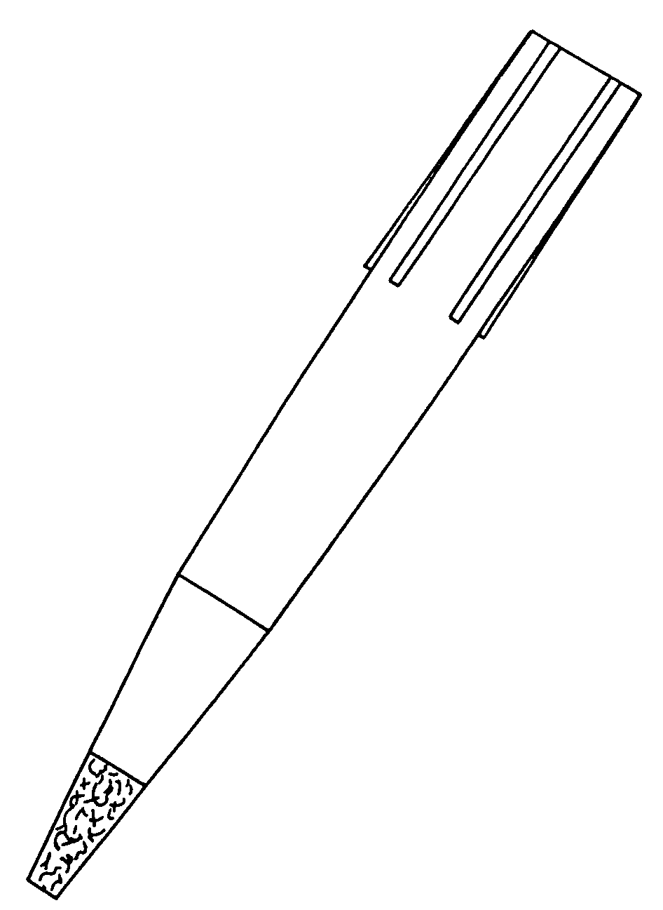
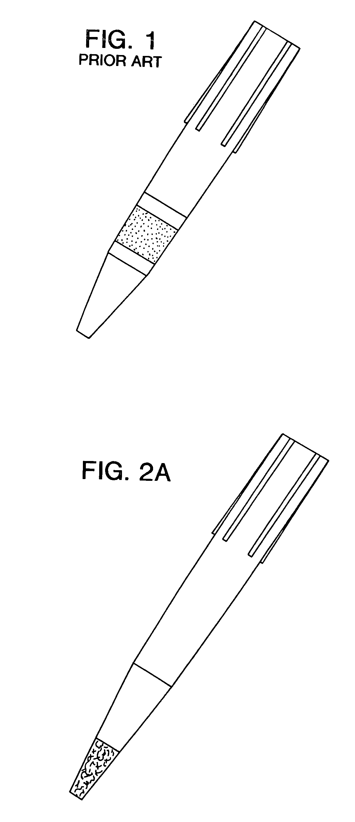
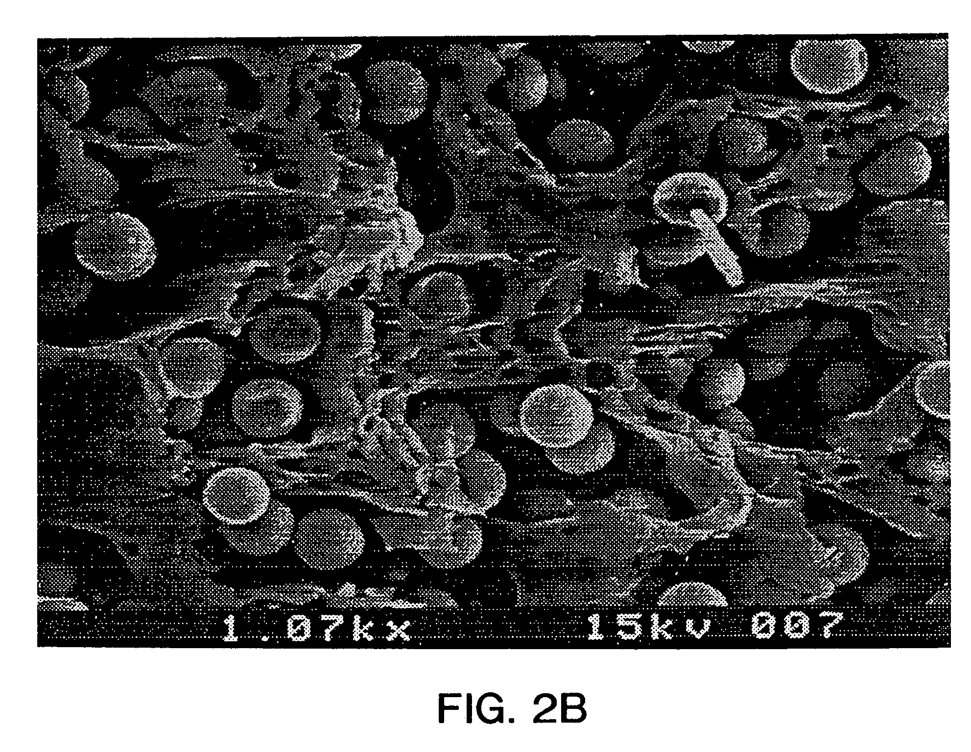
Image

Examples
example 1
Strong Cation Exchange (SCX) Silica in 20 μl Pipette Tips
[0057]In a suitable small vessel, 5 grams of a 7% (w / w) PVDF solution (Pennwalt Corp, KYNAR 761) was prepared in N,N-dimethyacetamide. To this, 1 gram of SCX, 200 Å, 15 μm (Millipore, PN 85864) spherical silica was added and mixed thoroughly with a spatula. The mixture was allowed to equilibrate for 2 hours at room temperature, then mixed again. A 20 μl fluted polypropylene disposable pipette tip was affixed to a common P-20 Pipetman (Gilson, Ranin, etc.) and the volume adjustment was set to 20 μl. The plunger was depressed to the bottom and the end of the pipette was placed into the casting solution. While carefully watching, the plunger was slowly raised to fill the tip with ca. 0.5–1 μl of casting solution. Once the tip contained sufficient liquid, equal pressure was maintained, and the pipette tip was removed and dipped into a bath of deionized water @ 60° C. for ca. 5 seconds. After this brief period, pressure was release...
example 2
C18 Silica in Common 200 μl Pipette Tips
[0058]In a suitable small vessel, 5 grams of a 6% (w / w) polysulfone solution (Amoco, P3500) was prepared in N-methyl-2-pyrrolidone. To this 2 grams of C18, 200 Å, 15 μm spherical silica (Millipore, PN 85058) was added and mixed thoroughly with a spatula. The mixture was allowed to equilibrate for 2 hours at RT., then mixed again. A 200 μl fluted polypropylene disposable pipette tip was affixed to a common P-200 Pipetman (Gilson, Ranin, etc.) and the volume adjustment was set to 200 μl. The plunger was depressed to the bottom and the end of the pipette was placed into the casting solution. While carefully watching, the plunger was slowly raised to fill the tip with ca. 2–5 μl of casting solution. Once the tip contained sufficient liquid, equal pressure was maintained, and the tip was removed and dipped into a bath of deionized water at room temperature for ca. 5 seconds. After this brief period, pressure on the plunger was released and water wa...
example 3
60 Å, 10 μm Normal Phase Silica in Wide Bore 1000 μl Pipette Tips
[0059]In a suitable small vessel, 6 grams of a 6% (w / w) cellulose acetate solution (Eastman Kodak, 398–60) was prepared in N-methyl-2-pyrrolidone. To this, 1 gram of 60 Å, 10 μm granular silica gel (Davison, Grade 710) was added and mixed thoroughly with a spatula. The mixture was allowed to equilibrate for 2 hours at room temperature, then mixed again. A wide bore 1000 μl polypropylene pipette was affixed to a common P-1000 Pipetman (Gilson, Ranin, etc.) and the volume adjust was set to 1000 μl. The plunger was depressed to the bottom and the end of the pipette was placed into the casting solution. While carefully watching, the plunger was slowly raised to fill the tip with ca. 10–25 μl of casting solution. Once the tip contained sufficient liquid, equal pressure was maintained, and the tip was removed and dipped into a bath of deionized water for ca. 5 seconds. After this brief period, pressure on the plunger was rel...
PUM
| Property | Measurement | Unit |
|---|---|---|
| Diameter | aaaaa | aaaaa |
| Volume | aaaaa | aaaaa |
| Permeability | aaaaa | aaaaa |
Abstract
Description
Claims
Application Information