Method and apparatus for stripping sulfur-containing compounds from hydrocarbon feed stock in hydrorefining of petroleum distillates

a technology of hydrorefining and sulfur-containing compounds, which is applied in the direction of hydrocarbon oil cracking, separation process, chemical/physical/physicochemical process, etc., can solve the problems of difficult hydrorefining of gas oil distillates, difficult operation, and difficulty in adequately reducing sulfur and nitrogen content in hydrorefining, etc., to achieve the effect of reducing sulfur content, nitrogen content and aromatic conten

Inactive Publication Date: 2006-02-21
JAPAN ENERGY CORP +1
View PDF7 Cites 30 Cited by
  • Summary
  • Abstract
  • Description
  • Claims
  • Application Information

AI Technical Summary

Benefits of technology

[0006]The first object of the present invention is to provide a hydrorefining method which can make sulfur content, nitrogen content, and aromatic content lower than with conventional hydrorefining methods.
[0007]The second object of the present invention is to provide a hydrorefining unit with a simple structure, and that can be made by simple modification of existing hydrorefining units.
[0009]With the hydrorefining unit of the present invention, liquid component flowed out from the first catalyst layer is held by a holding member provided between the first catalyst layer and the second catalyst layer and the hydrogen sulfide and ammonia in the liquid component can be stripped by introducing hydrogen from the hydrogen introduction part to this liquid component held in the holding member. As a result of this stripping, hydrorefining in the second catalyst layer can be started in an ambient atmosphere that does not comprise impurities such as hydrogen sulfide, ammonia, etc., and a hydrorefined product with a super-low sulfur content, super-low nitrogen content, and low aromatic content can be obtained. Hydrogen from the hydrogen introduction part also can be fed to the second catalyst layer. Therefore, with the unit of the present invention, it is possible to simultaneously feed hydrogen for stripping and hydrogen for hydrorefining at the second catalyst layer from the hydrogen feed source. Consequently, impurities such as hydrogen sulfide, ammonia, etc., can be easily removed using a simple unit structure.
[0010]It is preferred that the hydrogen introduction part of the unit of the present invention be arranged on the downstream side of the holding member and on the upstream side of the second catalyst layer. By arranging the hydrogen introduction part in this way, some of the hydrogen that has been introduced can rise to the holding member, while the remainder of the hydrogen can move toward the second catalyst layer together with liquid component that has flown out from the holding member.
[0011]It is preferred that the first catalyst layer, second catalyst layer, and holding member of the unit of the present invention be housed in a single reaction vessel. When constructed in this way, the unit of the present invention can be made easily by modifying ordinary hydrorefining units with a first catalyst layer and a second catalyst layer. In this case, the hydrogen introduction part can be provided between the holding member and the second catalyst layer.
[0014]By means of the present invention, hydrogen for stripping and hydrogen for hydrorefining can be shared and therefore, it is possible to make a hydrorefining plant with a simple structure and at low cost.

Problems solved by technology

However, the concentration of impurities, such as hydrogen sulfide, ammonia, etc., produced by hydrorefining contained in the hydrorefined hydrocarbons near the outlet of the catalyst layers rises and therefore, hydrorefining wherein contents of the sulfur and nitrogen are adequately reduced is difficult.
However, it is difficult to hydrorefine gas oil distillates in order to bring the sulfur content to 150 ppm or less, particularly 50 ppm or less, with the above-mentioned conventional unit and method.
In particular, there is a problem that the allowable range of the gas quantity of flow and feed oil quantity of flow with which stable operation is possible is narrow in hydrorefining units with which the previously mentioned hydrogen and feed oil are brought into contact with catalyst as cocurrent and therefore, operation is not simple.

Method used


Image

  • Method and apparatus for stripping sulfur-containing compounds from hydrocarbon feed stock in hydrorefining of petroleum distillates
  • Method and apparatus for stripping sulfur-containing compounds from hydrocarbon feed stock in hydrorefining of petroleum distillates
  • Method and apparatus for stripping sulfur-containing compounds from hydrocarbon feed stock in hydrorefining of petroleum distillates

Examples


embodiment 1

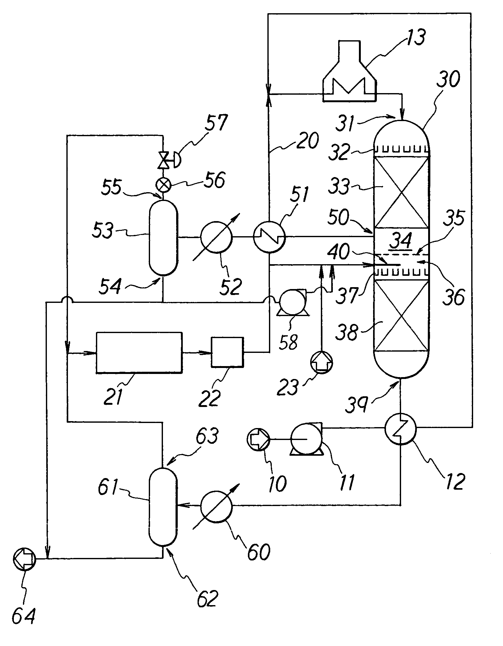
[0038]In the hydrorefining unit in FIG. 1, feed oil 10 is pressurized with pump 11, preheated by heat exchanger 12, mixed with hydrogen gas 20, and then heated by heater 13 to the temperature needed for hydrorefining. The mixed fluid consisting of the heated feed oil and hydrogen gas is fed to filler hole 31 formed at the top end of cylindrical reaction vessel 30, uniformly dispersed by first distributor tray 32, and descends to first catalyst layer 33 loaded with hydrorefining catalyst. The feed oil in the mixed fluid is partially hydrorefined in the presence of hydrogen and the same intermediate product flows out from the bottom end of first catalyst layer 33.

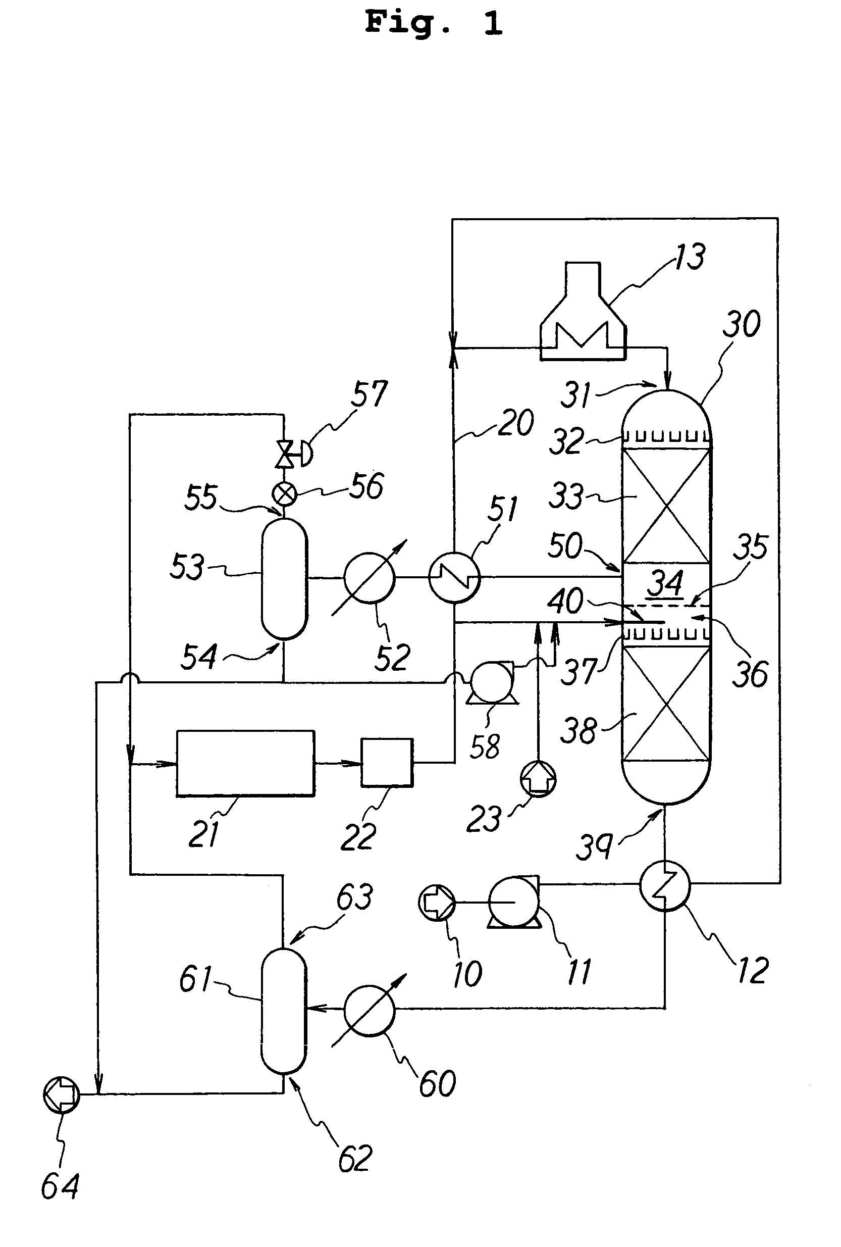
[0039]Valve tray 35 is provided at the bottom of first catalyst layer 33 with top space 34 interposed therebetween. Of the intermediate product that has flowed out from the bottom end of first catalyst layer 22, the vapor component accumulates in the top space, while the liquid component accumulates in valve tray 35. Structur...

embodiment 2

[0051]Another embodiment of the hydrorefining unit of the present invention will now be described in concrete terms using FIG. 3. The structure near valve tray 35 shown in FIG. 3 is approximately the same as the structure shown in FIG. 2, but it differs in terms of the arrangement of extraction nozzle 50. Extraction nozzle 50 in FIG. 3 is introduced into reaction vessel 30 via through hole 40a which runs through the side wall of reaction vessel 30, and further extends to top space 34 through diaphragm 35a of valve tray 35. When this type of structure is employed, the number of through holes leading to reaction vessel 30 can be reduced and therefore, the unit of the present invention can be obtained easily by modifying an ordinary reaction vessel used in hydrorefining.

embodiment 3

[0052]A modified hydrorefining unit of the present invention will now be described using FIG. 4. The hydrorefining unit in FIG. 3 is the same as the unit in Embodiment 1 with the exception that the valve tray in FIGS. 1 and 2 has been changed to packing material layer 110. Raschig rings packed on top of a base with multiple openings can be used as packing layer material 110. When the liquid component that flows out from first catalyst layer 33 passes through packing layer 110, it comes into contact as a countercurrent with the hydrogen that is rising up from packing material layer 110 and stripping is thereby performed with good efficiency.

[0053]The hydrorefining unit and method of the present invention have been explained in concrete terms with embodiments, but the present invention is not limited to these embodiments and can comprise various changes and modifications conceived of by a person skilled in the art. Hydrogen nozzle 40 was placed in the space underneath valve tray 35 in...


PUM

PropertyMeasurementUnit
temperatureaaaaaaaaaa
pressureaaaaaaaaaa

Abstract

A unit for hydrorefining of hydrocarbon crude oil comprising sulfur-containing compounds comprises first catalyst layer 33 and second catalyst layer 38, top space 34 for separating vapor component and liquid component, bottom space 36, and valve tray 35 that divides top space 34 and bottom space 36. Hydrogen released from hydrogen nozzle 40 placed in the bottom space is passed through liquid component that has accumulated in the valve tray and stripping of liquid components is performed. Hydrogen released from hydrogen nozzle 40 is again introduced, to second catalyst layer 38 as a cocurrent with the stripped liquid component. By stripping, it is possible to reduce the sulfur content, the nitrogen content and reduce the aromatic content of the hydrocarbon crude oil when compared to the conventional method. Since the hydrorefining unit has a simple structure, the unit can be easily made by modifying existing units.

Description

[0001]This application is the national phase under 35 U.S.C. § 371 of PCT International Application No. PCT / JP00 / 00147 which has an International filing date of Jan. 14, 2000, which designated the United States of America and was not published in English.TECHNICAL FIELD[0002]The present invention relates to hydrorefining of petroleum middle distillate, such as kerosene, gas oil, and particularly, to a hydrorefining apparatus and hydrorefining method for obtaining super-low-sulfur middle distillates with a sulfur content of 150 ppm or less.BACKGROUND ART[0003]A method for hydrorefining crude oil by mixing the crude oil with hydrogen, heating and bringing into contact with hydrorefining catalysts loaded in multiple catalyst layers is known as a typical hydrorefining method for obtaining low-sulfur gas oil with a sulfur content of 500 ppm or less. In this method, there are also cases wherein hydrogen is further introduced between the multiple catalyst layers. However, the concentration...

Claims


Application Information

Patent Timeline
Patent Type & Authority Patents(United States)
IPC IPC(8): C10G45/02B01J8/04C10G65/02C10G49/00C10G65/04
CPCC10G65/04C10G49/002
Inventor KOYAMA, HIROKITAKAHASHI, YUICHI
Owner JAPAN ENERGY CORP
Why Eureka
Try Eureka