
Kinetic sprayed electrical contacts on conductive substrates

a technology of electrical contacts and conductive substrates, applied in the field of electrical contacts, can solve the problems of difficult to maintain the uniform output of particles necessary to form a continuous layer, and the production of a continuous layer of particles is even more difficult, so as to achieve high surface-to-surface contact and reduce contact resistan

Inactive Publication Date: 2006-02-21
FLAME SPRAY IND
View PDF106 Cites 3 Cited by
  • Summary
  • Abstract
  • Description
  • Claims
  • Application Information

AI Technical Summary

Benefits of technology

[0015]Utilizing the apparatus disclosed in U.S. Pat. No. 6,139,913, the teachings of which are incorporated herein by reference, it was recognized that thick continuous layer coatings could be produced on conductive substrates in the production of electrical contacts. Such thick coatings are practical due to the mechanical bonds that are formed by impact impingement of the particles onto the substrate. These thicker continuous layer coatings are beneficial in producing electrical contacts since they provide low porosity, low oxide, low residual stress coatings that result in electrical contacts having greater longevity and durability.
[0018]In addition, the present invention provides the means for controlling the location of deposition of kinetic sprayed particles and the particle number density deposited in that location on the conductive substrate by simply controlling the feed rate of particles into the gas stream and the traverse speed of the substrate across the apparatus and / or nozzle. By doing so, the spray of conductive materials is controlled so that particles are only deposited on those portions that are to be stamped out as conductors.
[0019]This provides a tremendous advantage in processing. It substantially reduces waste of the conductive particles and aids in the reuse of substrate materials. Furthermore, there are no plating bath waste products or associated disposal costs.
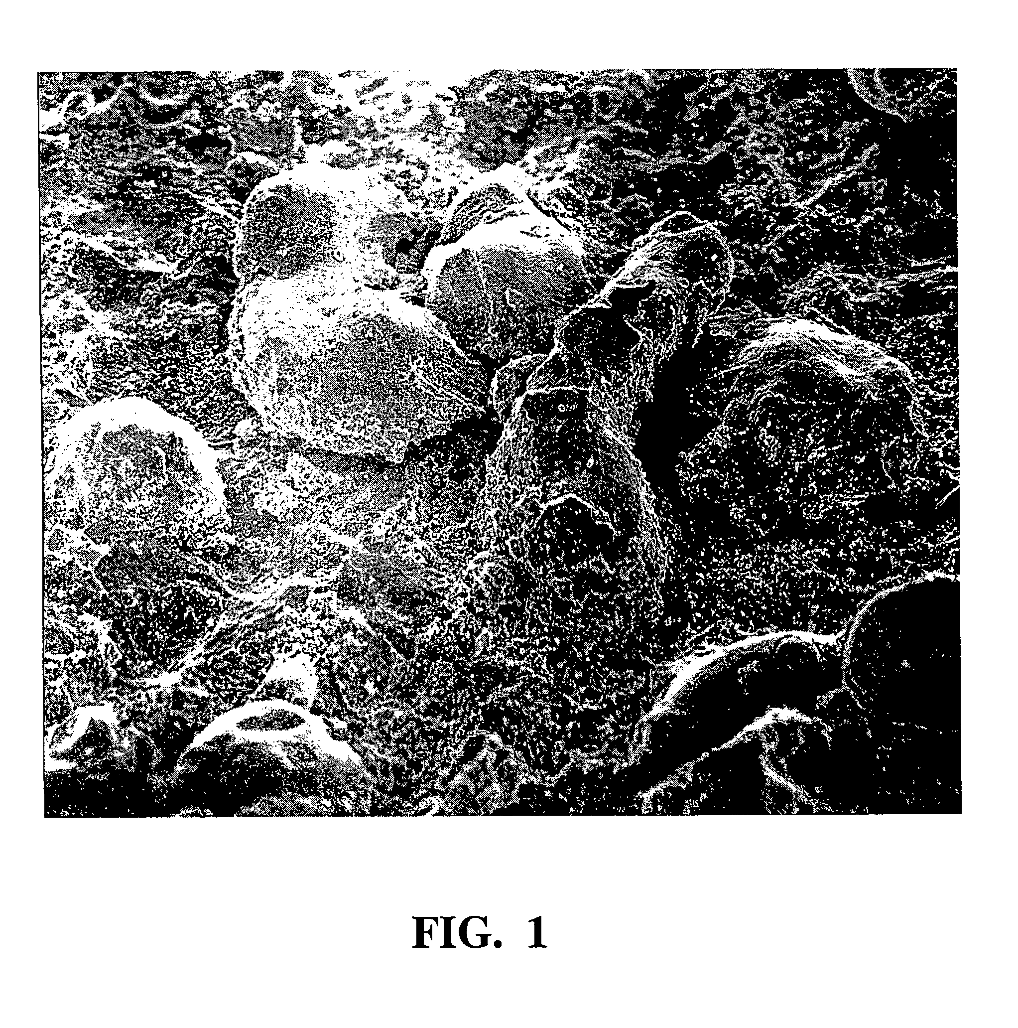
[0021]The present invention provides that particles can be kinetic sprayed onto conductors with sufficient energy to form direct mechanical bonds between the particles and the conductors in a pre-selected location and particle number density that promotes high surface-to-surface contact between the conductors with reduced contact resistance.

Problems solved by technology

When the feed rate of the particles into the gas stream is reduced, it is difficult to maintain a uniform output of particles necessary to form a continuous layer.
The production of a continuous layer of particles is even more problematic if the substrate is moved across the nozzle or vice versa.

Method used


Image

  • Kinetic sprayed electrical contacts on conductive substrates
  • Kinetic sprayed electrical contacts on conductive substrates
  • Kinetic sprayed electrical contacts on conductive substrates

Examples


Embodiment Construction

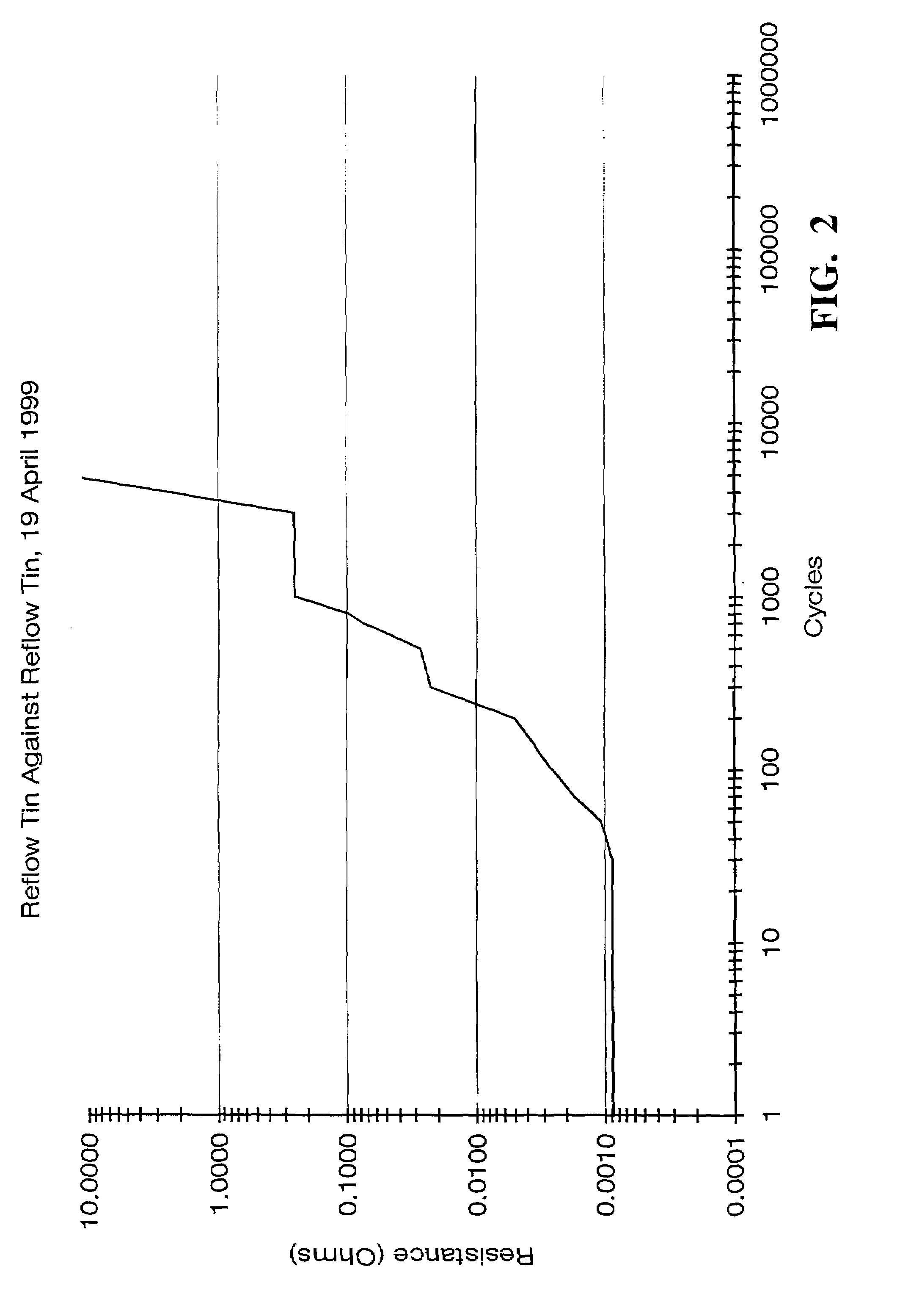
[0025]An electrical contact of the present invention preferably has a contact resistance of less than about 10 milli-ohms and more preferably less than about 2 milli-ohms (when measured with a 1 Newton load and a 1.6 mm radius gold probe per ASTM B667). However, it is well recognized that electrical contacts of any contact resistance fall within the scope of the invention. The electrical contact comprises first and second mated conductors. While more than two conductors may be used to form an electrical contact, two are preferred. The conductors are stamped out of conductive substrates made of any suitable conductive material including, but not limited, to copper, copper alloys, aluminum, brass, stainless steel and tungsten. It is preferred, however, that the substrate be made of copper.

[0026]In each contact of the present invention, at least one of the conductors comprises a plurality of spaced particles that have been embedded into the surface of the conductor in a pre-selected lo...


PUM

PropertyMeasurementUnit
Diameteraaaaaaaaaa
Diameteraaaaaaaaaa
Heightaaaaaaaaaa

Abstract

The present invention is directed to electrical contacts that comprise spaced electrically conductive particles embedded and bonded into the surface of conductors in which the particles have been kinetically sprayed onto the conductors with sufficient energy to form direct mechanical bonds between the particles and the conductors in a pre-selected location and particle number density that promotes high surface-to-surface contact and reduced contact resistance between the conductors.

Description

[0001]This is a division of application Ser. No. 09 / 974,243 filed on Oct. 9, 2001, now U.S. Pat. No. 6,685,988.TECHNICAL FIELD[0002]The present invention is directed to electrical contacts that comprise spaced particles embedded into the surface of conductors in which the particles have been kinetically sprayed onto the conductors with sufficient energy to form direct mechanical bonds between the particles and the conductors in a pre-selected location and particle number density that promotes high surface-to-surface contact and reduced contact resistance between the conductors. The method of making such electrical contacts is also provided.INCORPORATION BY REFERENCE[0003]U.S. Pat. No. 6,139,913, “Kinetic Spray Coating Method and Apparatus,” is incorporated by reference herein.BACKGROUND OF THE INVENTION[0004]Most electrical contacts are copper or copper alloy conductors with a tin-plated surface layer. The tin surface layer is a single continuous layer directly bonded to a clean non...

Claims


Application Information

Patent Timeline
IPC IPC(8): B32B15/02B32B15/04B32B15/20H01R13/03H01R4/58
CPCH01R4/58H01R13/03Y10T428/12104Y10T428/12708Y10T428/12736Y10T428/12486Y10T428/24851Y10T428/24917Y10T428/25Y10T428/12063Y10T428/12903
Inventor VAN STEENKISTE, THOMAS HUBERTDREW, GEORGE ALBERTGORKIEWICZ, DANIEL WILLIAMGILLISPIE, BRYAN A.
Owner FLAME SPRAY IND
Learn More