Instrument for measuring lifetime of fluorescene

a fluorescence lifetime and measuring device technology, applied in the direction of fluorescence/phosphorescence, luminescent dosimeters, optical radiation measurement, etc., can solve the problems of inability to use reliable measurement methods, inability to adjust and match the timing of streaks, and inability to achieve reliable measurement. reliable, high temporal resolution, and high precision

Inactive Publication Date: 2006-02-21
HAMAMATSU PHOTONICS KK
View PDF8 Cites 8 Cited by
  • Summary
  • Abstract
  • Description
  • Claims
  • Application Information

AI Technical Summary

Benefits of technology

[0014]The gate pulse for producing the fluorescence image in the detection medium is a short-time-width light pulse from a pulse light source as stated above. It is thus possible to make the positions of the fluorescence image and the times in the temporal change of the fluorescence phenomenon correspond to one another with high precision. Consequently, by observing the change in position (positional dependence) of the intensity or the like of the fluorescence image, the change over time (time dependence) of the fluorescence phenomenon can be measured efficiently with high temporal resolution, and hence it becomes possible to determine the fluorescence lifetime with high temporal resolution.
[0015]With such a measurement method, there is very little timing jitter, and hence

Problems solved by technology

However, with conventional measurement methods such as those mentioned above, measurement cannot be carried out with sufficient temporal resolution.
Moreover, it is difficult to adjust and match the timing of the streak sweeping for each measurement to femtosecond order.
With such a time domain, it is thus not possible to use a method in which reliable measurement results are obtained by carrying out measurement a plurality of times and totaling the measurement results.
This is a problem in particular with measurement such as fluorescence measurement in which extremely faint light is the subject of observation.
In this case, the duration of the birefringence at the Kerr gate which exhibits a large Kerr effect

Method used


Image

  • Instrument for measuring lifetime of fluorescene
  • Instrument for measuring lifetime of fluorescene
  • Instrument for measuring lifetime of fluorescene

Examples


first embodiment

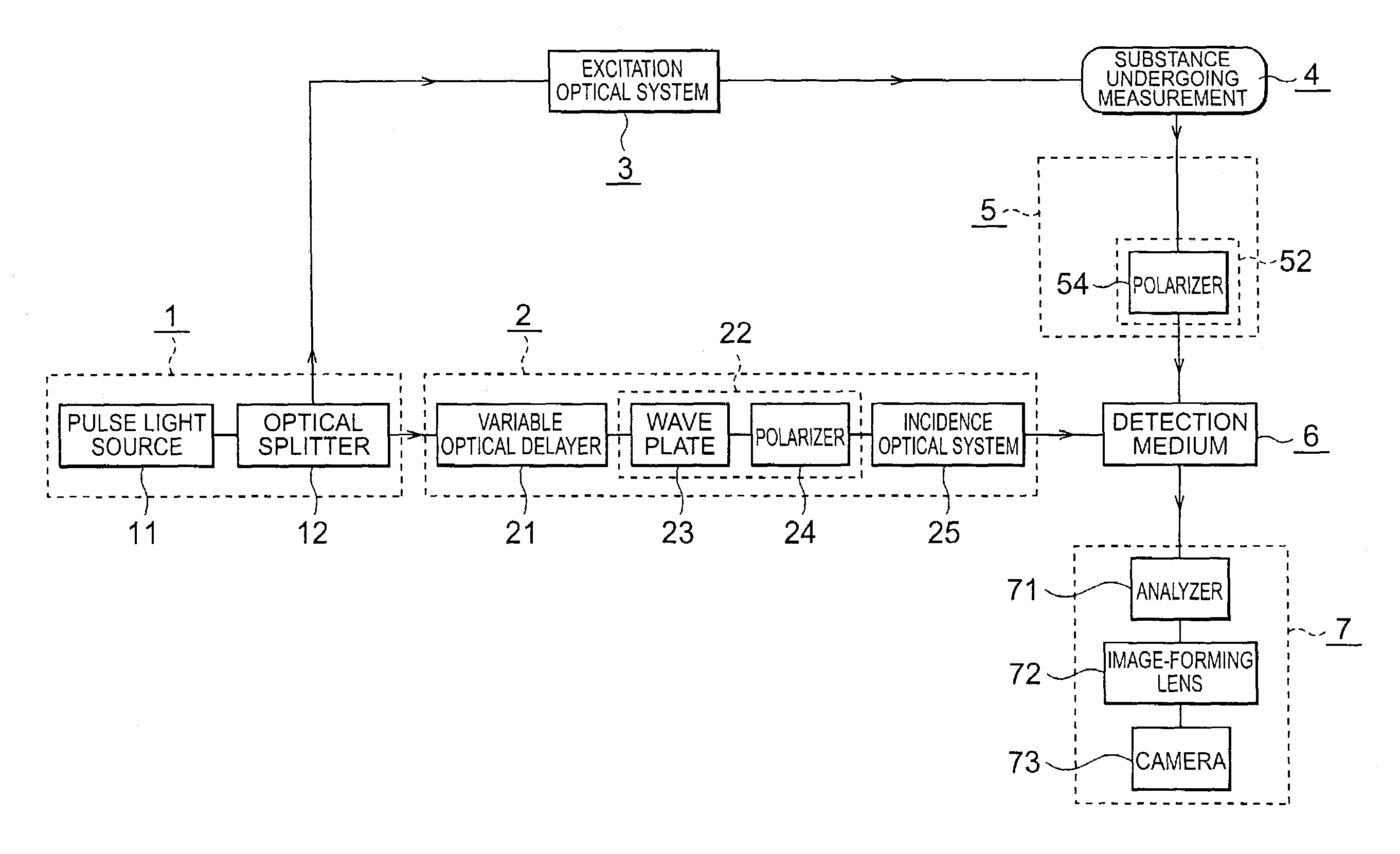
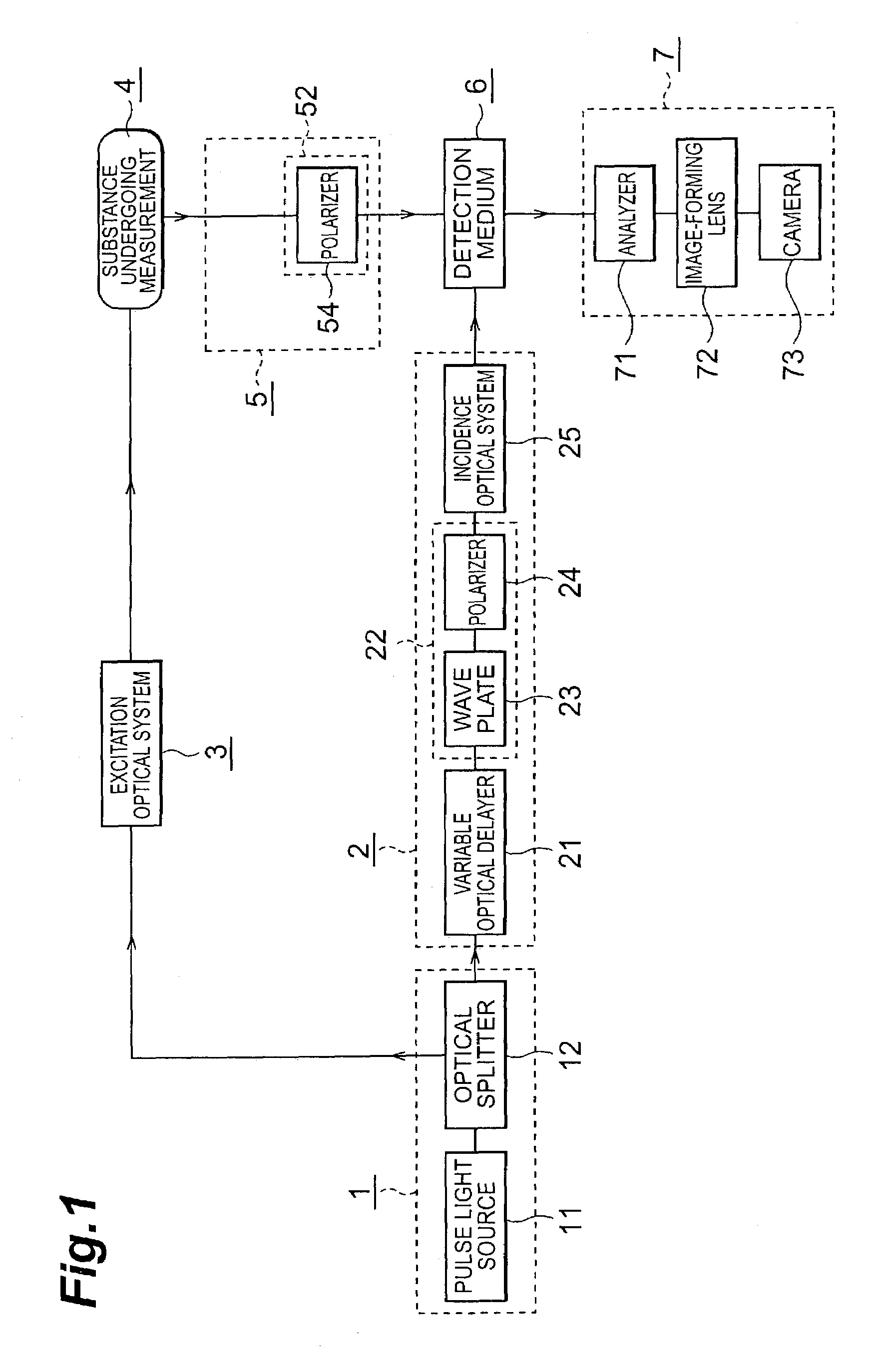
[0031]FIG. 1 is a block diagram showing the fluorescence lifetime measuring apparatus according to the present invention. The fluorescence lifetime measuring apparatus in the present embodiment is constituted from a light source part 1, a gate optical system 2, an excitation optical system 3, a fluorescence optical system 5, a detection medium 6, and a photodetection part 7.

[0032]The light source part 1 has an ultra-short pulse light source 11 that produces and outputs a light pulse, and an optical splitter 12. The light pulse outputted from the ultra-short pulse light source 11 is split by the optical splitter 12 into a first light beam that is led to the gate optical system 2, and a second light beam that is led to the excitation optical system 3.

[0033]The first light beam and the second light beam outputted from the light source part 1 are taken as a gate pulse and an excitation pulse respectively, and are led to the detection medium 6 and a substance under going measurement 4 re...

fifth embodiment

[0099]FIG. 11 is a block diagram showing the fluorescence lifetime measuring apparatus according to the present invention; here, a single pulse light source is not used as the light source part 1, but rather a separate gate pulse light source 11a and excitation pulse light source 11b are used respectively for the gate pulse for measuring the fluorescence and the excitation pulse for producing the fluorescence.

[0100]The timing of the excitation pulse, i.e. the timing of the fluorescence produced by the excitation pulse, relative to the gate pulse is controlled by a timing control circuit 15 in addition to the variable optical delayer 21. The timing control circuit 15 has a trigger circuit 16 and a delay circuit 17; using these, the two pulses can be synchronized, and moreover setting and changing of the time delay difference can be carried out. In this case, a constitution may be adopted in which neither the gate optical system 2 nor the excitation optical system 3 has a variable opt...


PUM


Abstract

A fluorescence component that passes through a region of a detection medium where a change in refractive index has been induced through a nonlinear optical effect produced in the detection medium by a gate pulse is observed as a fluorescence image by utilizing a change in polarization state. By observing the change in position of the fluorescence image while correlating with the change over time in the fluorescence, a fluorescence lifetime measuring apparatus is realized with which the change over time in the fluorescence, in particular the fluorescence lifetime, can be measured efficiently with high temporal resolution.

Description

TECHNICAL FIELD[0001]The present invention relates to a fluorescence lifetime measuring apparatus that can observe fluorescence emitted from a substance after irradiation with a light pulse.BACKGROUND ART[0002]With the development of laser technology with regard to femtosecond-domainultra-shortpulse lasers and the like, in recent years attention has focused on various phenomena that occur with a femtosecond time domain or on a femtosecond time-scale. One such phenomenon is the phenomenon of fluorescence emitted by a substance upon irradiation with a light pulse.[0003]If a substance is irradiated with such a femtosecond ultra-short light pulse, then fluorescence that changes over time with a femtosecond time domain can be obtained, for example the behavior of the fluorescence phenomenon on a femtosecond time-scale can be obtained. Examples of techniques carried out to observe such a fluorescence phenomenon are a method using a streak camera and a method of sampling measurement throug...

Claims


Application Information

Patent Timeline
IPC IPC(8): G01N21/64
CPCG01N21/6445G01N21/6408
Inventor FUJIMOTO, MASATOSHIAOSHIMA, SHINICHIROHOSODA, MAKOTOTSUCHIYA, YUTAKA
Owner HAMAMATSU PHOTONICS KK
Why Eureka
Try Eureka