Light-emitting device having light-emissive particles partially coated with intensity-enhancement material

Inactive Publication Date: 2006-02-21
CANON KK
View PDF24 Cites 13 Cited by
  • Summary
  • Abstract
  • Description
  • Claims
  • Application Information

AI Technical Summary

Benefits of technology

[0034]In short, a light-emitting device configured and manufactured according to the invention has improved performance and increased lifetime. The present light-emitting device can readily be manufactured in a large scale production environment. By providing the particles with the pre

Problems solved by technology

The so-released gases can contaminate the display and cause it to degrade.
Also, full coatings 44 may detrimentally affect the formation of the light-emi

Method used


Image

  • Light-emitting device having light-emissive particles partially coated with intensity-enhancement material
  • Light-emitting device having light-emissive particles partially coated with intensity-enhancement material
  • Light-emitting device having light-emissive particles partially coated with intensity-enhancement material

Examples


Embodiment Construction

General Considerations

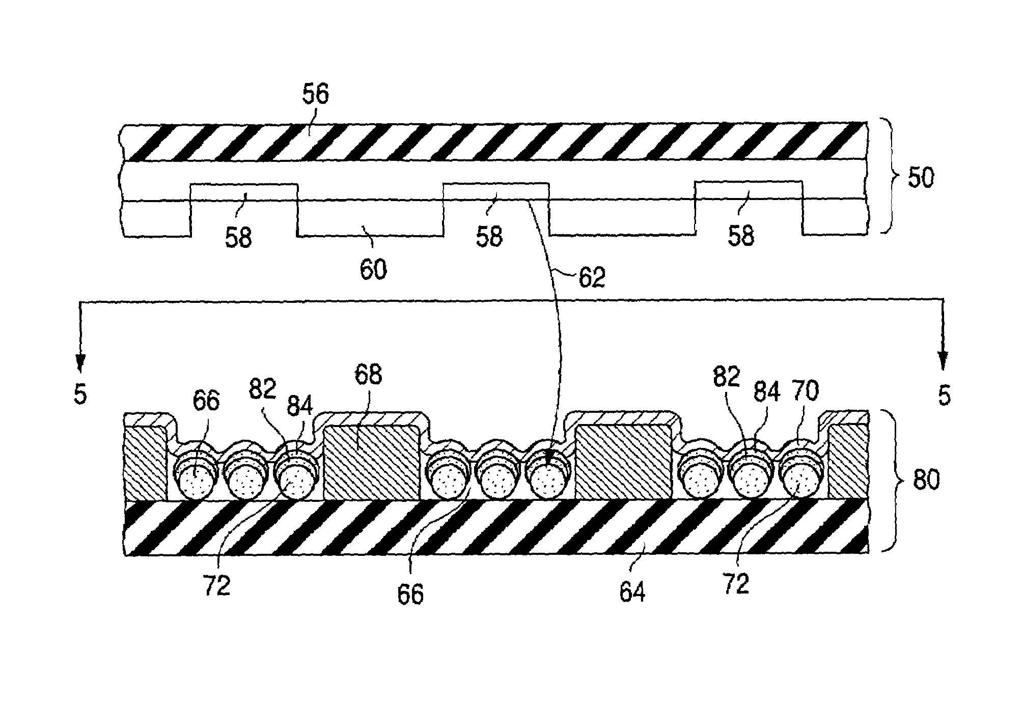
[0053]Various configurations are described below for flat-panel CRT displays having light-emitting devices configured according to the invention. Each flat-panel CRT display is typically suitable for a flat-panel television or a flat-panel video monitor for a personal computer, a laptop computer, a workstation, or a hand-held device such as a personal digital assistant.

[0054]Each of the present flat-panel CRT displays is typically a color display but can be a monochrome, e.g., black-and-green or black-and-white, display. Each light-emissive region and the corresponding oppositely positioned electron-emissive region form a pixel in a monochrome display, and a sub-pixel in a color display. A color pixel typically consists of three sub-pixels, one for red, another for green, and the third for blue.

[0055]In the following description, the term “electrically insulating” or “dielectric” generally applies to materials having a resistivity greater than 1010 ohm-cm. The ...


PUM


Abstract

A light-emitting device (52) suitable for a flat-panel cathode-ray tube display contains a light-emissive region (66) formed over a plate (64). The light-emissive region contains a plurality of light-emissive particles (72). Part of the outer surface of each of a group of the light-emissive particles is conformally covered with a group of intensity-enhancement coatings (82 and 84).

Description

CROSS-REFERENCE TO RELATED APPLICATION[0001]This is a division of U.S. patent application Ser. No. 09 / 823,815, filed 30 Mar. 2001, now U.S. Pat. No. 6,812,636.FIELD OF USE[0002]This invention relates to the configuration and manufacture of light-emitting devices suitable for use in flat-panel displays such as flat-panel cathode-ray tube (“CRT”) displays.BACKGROUND ART[0003]A flat-panel display CRT display typically consists of an electron-emitting device and an oppositely situated light-emitting device. The electron-emitting device, or cathode, contains electron-emissive elements that emit electrons across a relatively wide area. An anode in the light-emitting device attracts the electrons toward light-emissive regions distributed across a corresponding area in the light-emitting device. The anode can be located above or below the light-emissive regions. In either case, the light-emissive regions emit light upon being struck by the electrons to produce an image on the display's view...

Claims


Application Information

Patent Timeline
IPC IPC(8): H01J1/62H01J9/22H01J1/70H01J1/74H01J29/18H01J29/28H01J29/32H01J29/58H01J29/94H01J31/12
CPCH01J1/70H01J1/74H01J29/58H01J29/28H01J29/325H01J29/185
Inventor PORTER, JOHN D.PEARSON, ROGER A.KAJIWARA, KAZUOKATO, HARUOPAN, LAWRENCE S.PEI, SHIYOUFAHLEN, THEODORE S.
Owner CANON KK
Why Eureka
Try Eureka