Band pass interferometer with tuning capabilities

a band pass interferometer and tuning capability technology, applied in the field of improved band pass interferometers, can solve the problems of generating fringes, adding complexity to the system, and increasing power losses, and achieves reliable operation and easy manufacturing and alignment.

Inactive Publication Date: 2006-02-21
ROCTEST LTEELTD
View PDF16 Cites 24 Cited by
  • Summary
  • Abstract
  • Description
  • Claims
  • Application Information

AI Technical Summary

Benefits of technology

[0024]It is also an object of this invention to make the filter tunable by external means to change the phase shift of the light beam in each and every pass of the beam between two successive internal reflections, the external control mean changing simultaneously the phase shift of each and every output beam the thus maximizing the control efficiency.
[0038]In accordance with a sixth aspect of the present invention, the setup comprising the two plane parallel reflective surfaces does not constitute a resonant cavity for the input beam and instead enables a narrow and collimated input beam incident at a non-zero angle on the totally reflective surface to split into multiple output beams having very well controlled amplitudes and phase relationships.

Problems solved by technology

The problem in this case is to generate each carrier with its specific wavelength at the source side and to select only one carrier (wavelength) at a time per communication channel at the receiver side.
The multiplexer / demultiplexer introduces additional power losses and adds overall complexity to the system.
All of these rays interfere between them and generate fringes in the far field.
The main drawback of this approach is that the bandwidth depends on the incidence angle to Fabry-Perot filter, i.e. the bandwidth is not constant in the tuning range of the filter.
However, comments about the tuning range, transmission and bandwidth in the passband, and diffraction losses are not disclosed and accordingly are left up to speculation.
While the center wavelength range is acceptable for DWDM applications, the slopes of the transfer functions are unfortunately very mild.
However, the limitation with this approach comes from the tuning speed.
However, these filters have some important drawbacks: low tuning range, wide passband because of their low-order mode of operation, high diffraction losses because of the poor optical quality of the mirrors or Bragg reflectors and difficulties in connecting with optical fibers.
The major drawback using MEM technology to build the Fabry-Perot interferometer is the open loop operation, which makes impossible an accurate control of the displacement and of the position of the spherical mirror, and implicitly a bad control of the transmission characteristic.
Though the half symmetric cavity has the maximum mechanical stability among all the configuration of Fabry-Perot interferometers, this advantage cannot compensate the disadvantages of the open-loop operation of MEM technology.
This approach has some major drawbacks: mild slopes between the bandpass and the rejection bands when covering the spectral range for DWDM applications and strong polarization dependence.
While each have their own desirable characteristics, none provide for the required insertion loss in the passband, attenuation in the rejection bands, or the required slope of the transfer characteristic between the transmission band and the rejection bands.

Method used


Image

  • Band pass interferometer with tuning capabilities
  • Band pass interferometer with tuning capabilities
  • Band pass interferometer with tuning capabilities

Examples


Embodiment Construction

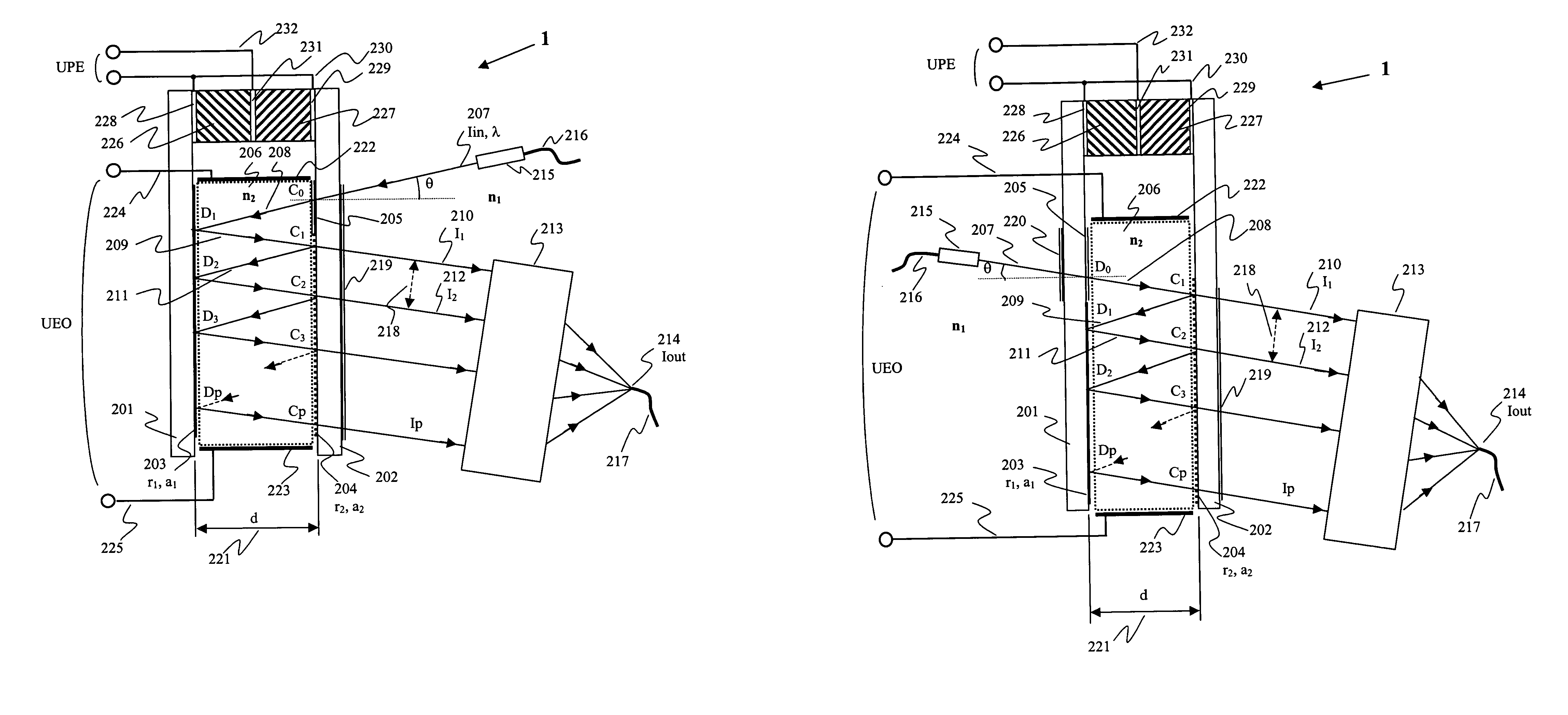
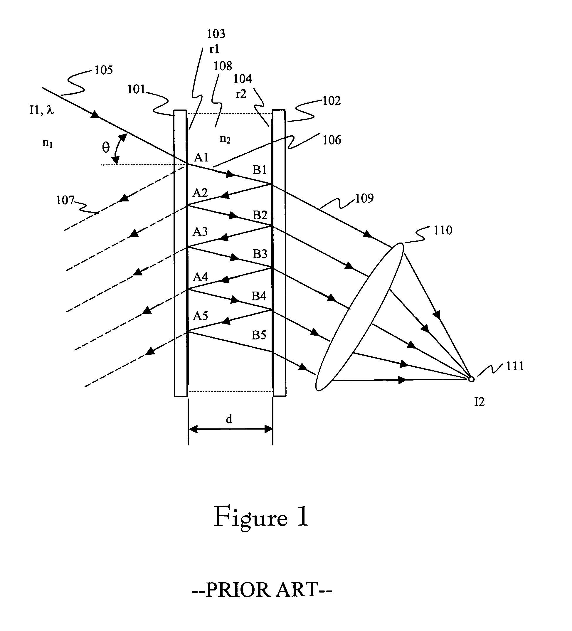
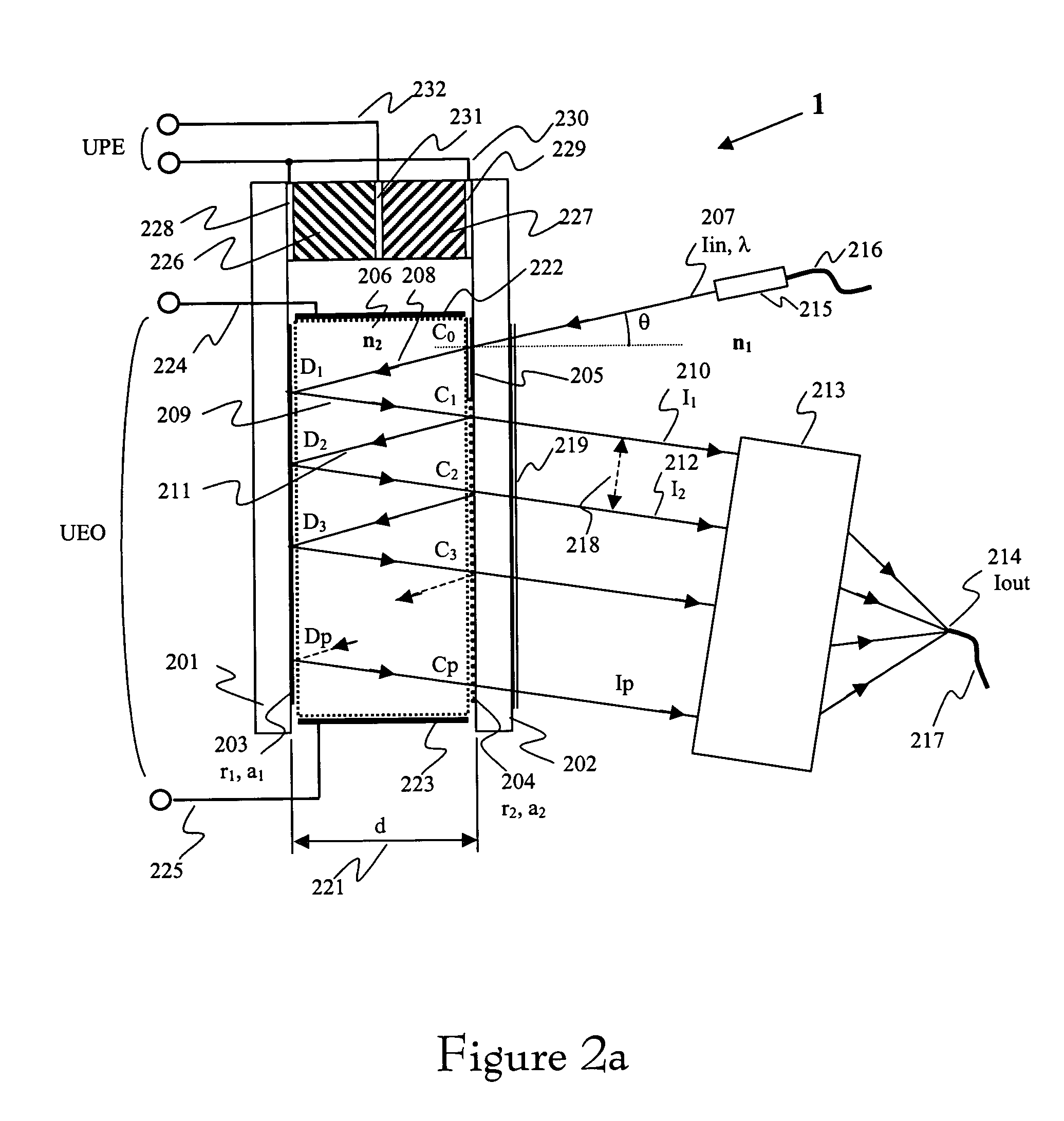
[0050]In the following detailed description of the embodiments, reference is made to the accompanying drawings which form a part hereof, and in which is shown by way of illustration specific embodiments in which the invention may be practiced. These embodiments are described in sufficient detail to enable those skilled in the art to practice the invention, and it is to be understood that other embodiments may be utilized and that structural, logical and electrical changes may be made without departing from the spirit and scope of the present inventions. The following detailed description is, therefore, not to be taken in a limiting sense, and the scope of the present inventions is defined only by the appended claims. The leading digit(s) of the reference numbers in the Figures usually correspond to the figure number, with the exception that identical components which appear in multiple figures are identified by the same reference numbers.

[0051]One purpose of the present invention is...


PUM


Abstract

An improved band pass interferometer for use as a high resolution wavelength selection unit comprising, as main elements, an input optical port (optical fiber) together with a fiber optic collimator for generating a narrow incoming collimated beam, two plane-parallel highly reflective surfaces with low reflection losses, one being totally reflective, (i.e. very little intensity of the light beam incident thereon should pass through the reflective surface,) the other being partially reflective, (i.e., a portion of a reflected light beam, more specifically its intensity, incident thereon should pass through the partially reflective surface becoming an output beam,) which splits the incoming narrow incoming collimated beam into a finite number of output beams, an optical medium located between the reflective surfaces, and a beam focusing element which collects all the output beams and focuses them into an output optical port (optical fiber). There is also provided a refractive index adjuster, such as, e.g., an electro-optical element, that changes the refractive index of the optical medium between the reflective surfaces using, preferably, an electro-optical control voltage. There is further provided an adjustable spacer, such as, e.g., a piezo-electrical element, that changes the spacing between the reflective surfaces using, preferably, a piezo-electric control voltage. The coherent beam emerging from the input port is collimated and is sent to two parallel reflective surfaces, one totally reflective, the other partially reflective, generating in this way a finite number of output beams, which are collected and focused into a focused spot by a converging element, usually a lens system. At the recombination point, which is the entrance aperture into the output optical port, all the multiple beams generated by the two mirrors setup, interfere. The output beam resulting from the interference of those multiple output beams is available as the output beam of the device. The transmission function, which is the ratio between the intensity available at the output port versus the intensity at the input port, strongly depends on the phase shift introduced between the multiple output beams by the beam-splitting element, realized with the two mirrors. The tuning principle of the said interferometer is to select only one wavelength at its output by changing either the spacing between the mirrors using the Piezo-electric control voltage or the refractive index of the media between them using the electro-optical control voltage, which leads to a shifting of the transmission maximum into a broad wavelength range, keeping also very good insertion loss or transmission efficiency for the selected wavelength and a constant bandwidth in the whole working range.

Description

CROSS-REFERENCE TO RELATED APPLICATIONS[0001]Not ApplicableSTATEMENT REGARDING FEDERALLY SPONSORED RESEARCH OR DEVELOPMENT[0002]Not ApplicableREFERENCE OF A “MICROFICHE APPENDIX”[0003]Not ApplicableBACKGROUND[0004]1. Field of Invention[0005]This invention relates to wavelength selection devices and more particularly to an improved band pass interferometer, which, among other things, has a defined passband, has polarization insensitivity, has low insertion loss, is reliable and is cost effective. In at least one of several preferred embodiments, the improved interferometer is also tunable.[0006]2. Brief Description of the Prior Art[0007]Optical communications system have been proliferating rapidly because of their high bandwidth, made available by the carrier frequency, in the hundreds of THz range, which corresponds to (0.9 . . . 1.6) μm wavelength range. (Throughout the description of this invention, either wavelength or frequency will be interchangeably used, depending on the cont...

Claims


Application Information

Patent Timeline
Patent Type & Authority Patents(United States)
IPC IPC(8): G01B9/02G02B6/34
CPCG02B6/29358G02B6/29395G02B6/29389
Inventor MIRON, NICOLAE
Owner ROCTEST LTEELTD
Why Eureka
Try Eureka