Direct conversion receiver having a gain-setting dependent filter parameter

a direct conversion and filter parameter technology, applied in the direction of gain control, amplitude demodulation, digital transmission, etc., can solve the problems of reducing device volume, direct conversion architecture also involves serious drawbacks, and removal from the signal spectrum, so as to achieve rapid adaptation to any dc step

Active Publication Date: 2006-02-21
MEDIATEK INC
View PDF18 Cites 19 Cited by
  • Summary
  • Abstract
  • Description
  • Claims
  • Application Information

AI Technical Summary

Benefits of technology

[0009]Generally, various embodiments are directed to direct conversion receiver devices and methods for operating the same, wherein a digital automatic gain control is performed to select one of a plurality of discrete gain settings of a variable gain amplifier in response to the measured baseband signal. The direct conversion receiver includes a filter unit adapted to operate in a first operation mode in which the filter unit exhibits the filter characteristics required to provide an appropriate baseband signal for a relatively stable RF signal input to the receiver. In a second operation mode of the filter unit the filter characteristics are modified such that a filter settling time is significantly shorter than in the first operation mode so that the filter unit allows a rapid adaptation to any DC step provided to the filter unit from a preceding amplifier stage.
[0010]Changing the operation mode of the filter unit may be accomplished by changing the value of at least one filter parameter. In this way, gain adaptation to the received RF signal is significantly accelerated while maintaining loop stability.

Problems solved by technology

Moreover, due to the lack of bulky, high-quality LC filters, which may not be easily integrated into a semiconductor substrate in the foreseeable future, the baseband components of a direct conversion device may directly be formed on a silicon chip, thereby significantly reducing device volume.
Except for the advantages mentioned so far, the direct conversion architecture also involves serious drawbacks compared to the superheterodyne architecture.
Due to the nature of the direct conversion of the radio frequency signal into the baseband signal, low frequency signals and DC components may be part of the down-converted signal spectrum, and thus spurious DC components may not be removed from the signal spectrum.
Moreover, any slight mismatch of the local oscillator to the frequency and phase of the incoming RF signal leads to a DC offset that may possibly not be distinguished from low frequency data components.
A further issue in RF receivers is the adaptation of the degree of signal amplification to the received radio frequency signal strength.
As a consequence, the additional DC offset may result in an unstable automatic gain control loop.
Although the provision of such high pass filters may significantly improve the automatic gain controlling, a DC offset created by gain switching at the amplifier output entails nevertheless a step response of the high pass filter, which, in turn, requires—due to the very low cut-off frequency—a relatively long settling time, so that an accurate measurement of the baseband signal necessitates a long measurement period, thereby preventing the automatic gain control from rapidly responding to a fast RF signal variation, which especially occurs upon receiving of an RF signal burst indicating the imminent transmission of data.
A long settling time of the automatic gain control may therefore lead to the loss of data or may require the repeating of the respective data packet.

Method used


Image

  • Direct conversion receiver having a gain-setting dependent filter parameter
  • Direct conversion receiver having a gain-setting dependent filter parameter
  • Direct conversion receiver having a gain-setting dependent filter parameter

Examples


Embodiment Construction

[0020]It is to be noted that although the present invention is described with reference to the embodiments as illustrated in the following detailed description and in the accompanying drawings, the detailed description as well as the drawings are not intended to limit the present invention to the particular embodiments disclosed therein, but rather the described embodiments merely exemplify the various aspects of the present invention, the scope of which is defined by the appended claims.

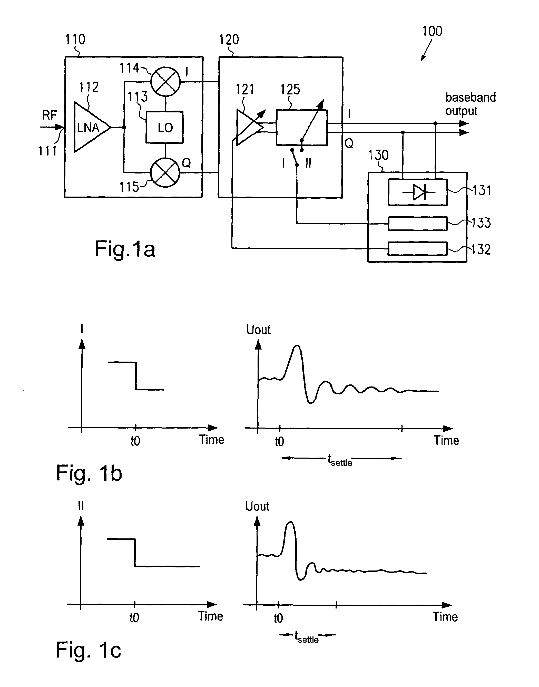
[0021]With reference to FIGS. 1a–1c, one illustrative embodiment will now be described that is directed to a baseband signal path usable in a direct conversion receiver, wherein digital automatic gain controlling is performed such that upon changing the discrete gain setting of a variable gain amplifier at least one parameter of a filter unit is changed to switch the filter unit from a first operation mode into a second operation mode that allows the filter unit to rapidly settle in response to a DC...


PUM


Abstract

In a direct conversion radio frequency receiver, an automatic gain control is implemented that allows changing the operation mode of a filter unit in the baseband section of the receiver such that in a first operation mode filter capacities are selected to provide desired output signal characteristics, whereas in a second operation mode the filter settling time is significantly reduced in order to speed up gain adaptation and to improve gain loop stability. In one embodiment the cut-off frequency of a high pass filter and the Q-factor of a subsequent low pass filter are increased and decreased respectively upon changing the gain setting of a variable gain amplifier to accelerate settling of the filter.

Description

FIELD OF THE PRESENT INVENTION[0001]The present invention generally relates to radio frequency (RF) receivers having a direct conversion architecture, wherein an automatic gain control is performed so as to rapidly adapt a variable gain amplifier to the received RF signal level.DESCRIPTION OF THE RELATED ART[0002]In radio receivers, the so-called direct conversion architecture is increasingly used, as in these devices down-conversion of the radio frequency signal into the baseband signal in a single step without the creation of an intermediate frequency signal is accomplished, thereby allowing the elimination of bulky, high-quality intermediate frequency filters. Moreover, since amplification and filtering mainly takes place in the baseband section, current-consuming high frequency amplifiers, necessary for signal amplification at intermediate frequencies, may be replaced by amplifiers and filters operating at baseband. The aspect of reduced power consumption is especially important...

Claims


Application Information

Patent Timeline
Patent Type & Authority Patents(United States)
IPC IPC(8): H04B1/06H03G3/30H04B1/30
CPCH04B1/30H03G3/3068
Inventor KLUGE, WOLFRAMDATHE, LUTZHONIG, JORG
Owner MEDIATEK INC
Why Eureka
Try Eureka