
Glucose sensor

a technology of glucose sensor and glucose, which is applied in the field of glucose sensor, can solve the problems of risk of enzyme denaturation, and insufficient amount of enzyme that reacts with the substra

Inactive Publication Date: 2006-02-28
PHC HLDG CORP
View PDF37 Cites 219 Cited by
  • Summary
  • Abstract
  • Description
  • Claims
  • Application Information

AI Technical Summary

Benefits of technology

[0041]The reaction layer of the biosensor of the present invention may contain a hydrophilic polymer. By adding a hydrophilic polymer to the reaction layer, it is possible to prevent separation of the reaction layer from the electrode system surface or the base plate surface. Moreover, since the hydrophilic polymer has the effect of preventing cracks in the reaction layer surface, it is effective for an increase of the reliability of the biosensor.

Problems solved by technology

Since the enzyme is composed mainly of protein, if the enzyme is exposed to moisture in the air, etc. over a long period, there is a risk of the denaturation of the enzyme.
Moreover, in an extreme case, there is a risk of the inactivation of the enzyme.
For this reason, if the sensor is stored for a long time, the enzyme activity is lowered and the amount of enzyme that reacts with the substrate becomes insufficient, and thus there is a possibility that the resultant response current value is not proportional to the concentration of the substrate.
However, in the case where the PQQ-GDH is used as the enzyme of the glucose sensor, it has been revealed that there is a problem that the response value is lowered by storage.
It is impossible to always use the sensor at a certain time after the fabrication of the sensor.
Hence, with a sensor whose response value will be lowered by storage, it is impossible to accurately quantify the concentration of glucose.

Method used


Image

  • Glucose sensor
  • Glucose sensor
  • Glucose sensor

Examples


example 1

[0065]After forming the CMC layer 7a in the same manner as in Comparative Example 1, 5 μl of a mixed aqueous solution containing 1000 U / ml of PQQ-GDH, 50 mM of potassium ferricyanide and 40 mM of potassium gluconate was dropped onto the CMC layer 7a and dried to form the layer 7b. A glucose sensor was fabricated in such a manner.

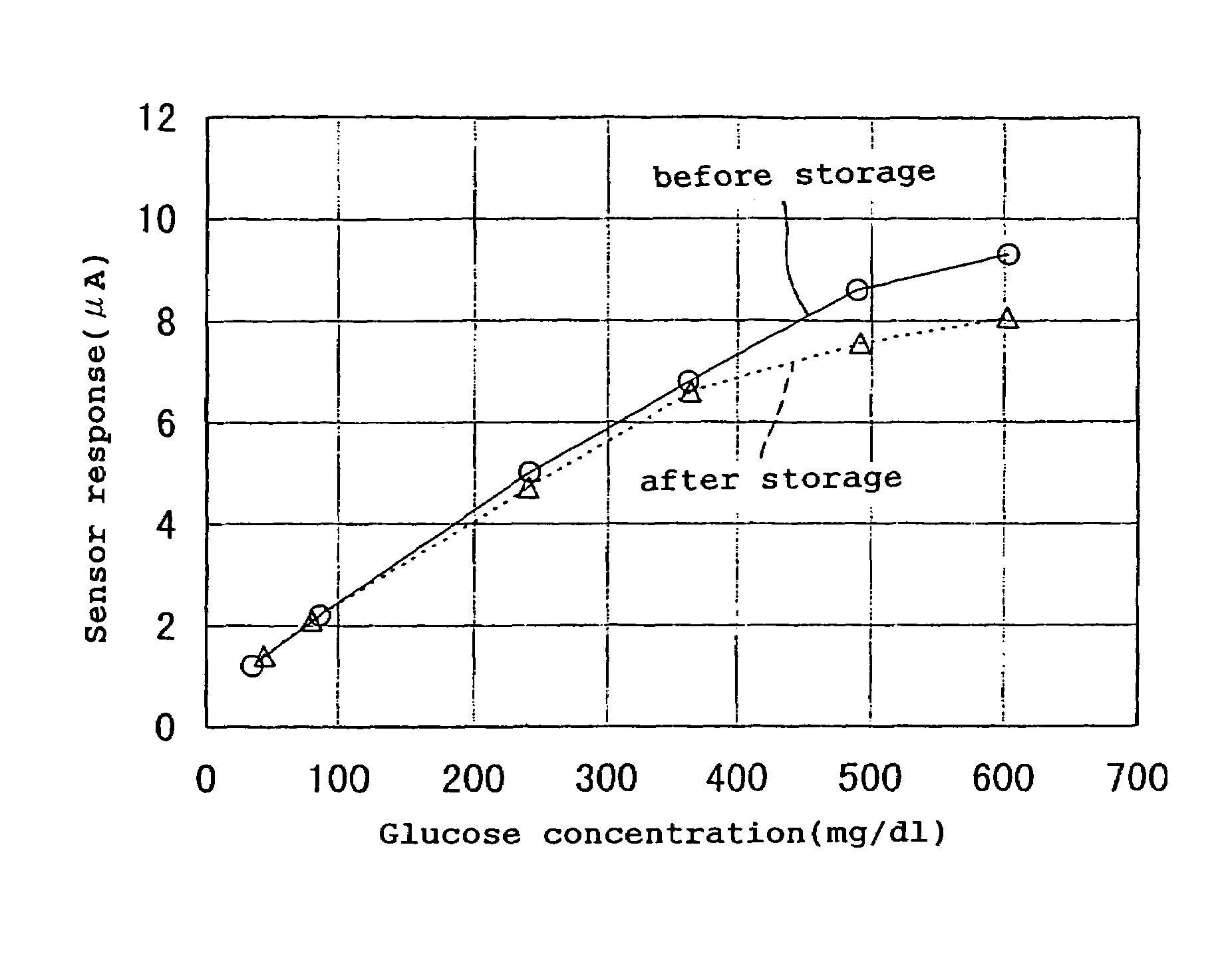
[0066]Next, in the same manner as in Comparative Example 1, the response characteristic graph was produced for the sensor immediately after the fabrication and the sensor after being stored in a sealed container containing silica gel for one week at 40° C. The results are shown in FIG. 4. It would be understood from FIG. 4 that there is a certain correlation between the glucose concentration and the response current value. It would be understood by a comparison with Comparative Example 1 that the sensor of this example had a smaller lowering in the response current value in the response after the one-week storage at 40° C., particularly in a range of not les...

example 2

[0068]After forming the CMC layer 7a in the same manner as in Comparative Example 1, 5 μl of a mixed aqueous solution containing 1000 U / ml of PQQ-GDH, 50 mM of potassium ferricyanide, 40 mM of potassium gluconate and 0.5 mM of potassium hydrogen phthalate was dropped onto the CMC layer 7a and dried to form the layer 7b. A glucose sensor was fabricated in such a manner.

[0069]In the same manner as in Comparative Example 1, the response characteristic graph was produced for the sensor immediately after the fabrication and the sensor after being stored in a sealed container containing silica gel for one week at 40° C. The results are shown in FIG. 6. It would be understood from FIG. 6 that there is almost no difference in the response characteristics between the sensor immediately after the fabrication and the sensor after the one week storage at 40° C., and the storage characteristic of the sensor of this example is significantly improved in comparison with Comparative Example 1.

[0070]...

example 3

[0071]After forming the CMC layer 7a in the same manner as in Comparative Example 1, 5 μl of a mixed aqueous solution containing 1000 U / ml of PQQ-GDH, 50 mM of potassium ferricyanide, 40 mM of potassium gluconate and 0.5 mM of maleic acid was dropped onto the CMC layer 7a and dried to form the layer 7b. A glucose sensor was fabricated in such a manner.

[0072]In the same manner as in Comparative Example 1, the response characteristic graph was produced for the sensor immediately after the fabrication and the sensor after being stored in a sealed container containing silica gel for one week at 40° C. The results are shown in FIG. 8. It would be understood from FIG. 8 that there is almost no difference in the response characteristics between the sensor immediately after the fabrication and the sensor after the one-week storage at 40° C., and the storage characteristic of the sensor of this example is improved in comparison with Comparative Example 1.

[0073]FIG. 9 shows a comparison of th...


PUM

PropertyMeasurementUnit
concentrationaaaaaaaaaa
voltageaaaaaaaaaa
temperatureaaaaaaaaaa

Abstract

The present invention provides a high-performance glucose sensor having excellent storage stability and an improved response characteristic. This sensor comprises: an electrically insulating base plate; an electrode system including at least a working electrode and a counter electrode formed on the base plate; and a reaction layer containing at least pyrrolo-quinoline quinone dependent glucose dehydrogenase, formed in contact with or in the vicinity of the electrode system, and the reaction layer contains at least one kind of additive selected from the group consisting of gluconic acid and salts thereof.

Description

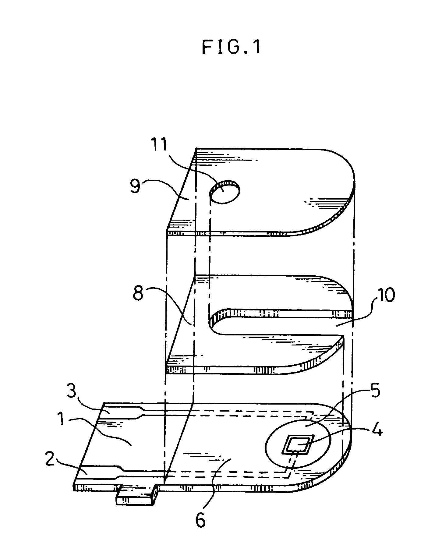
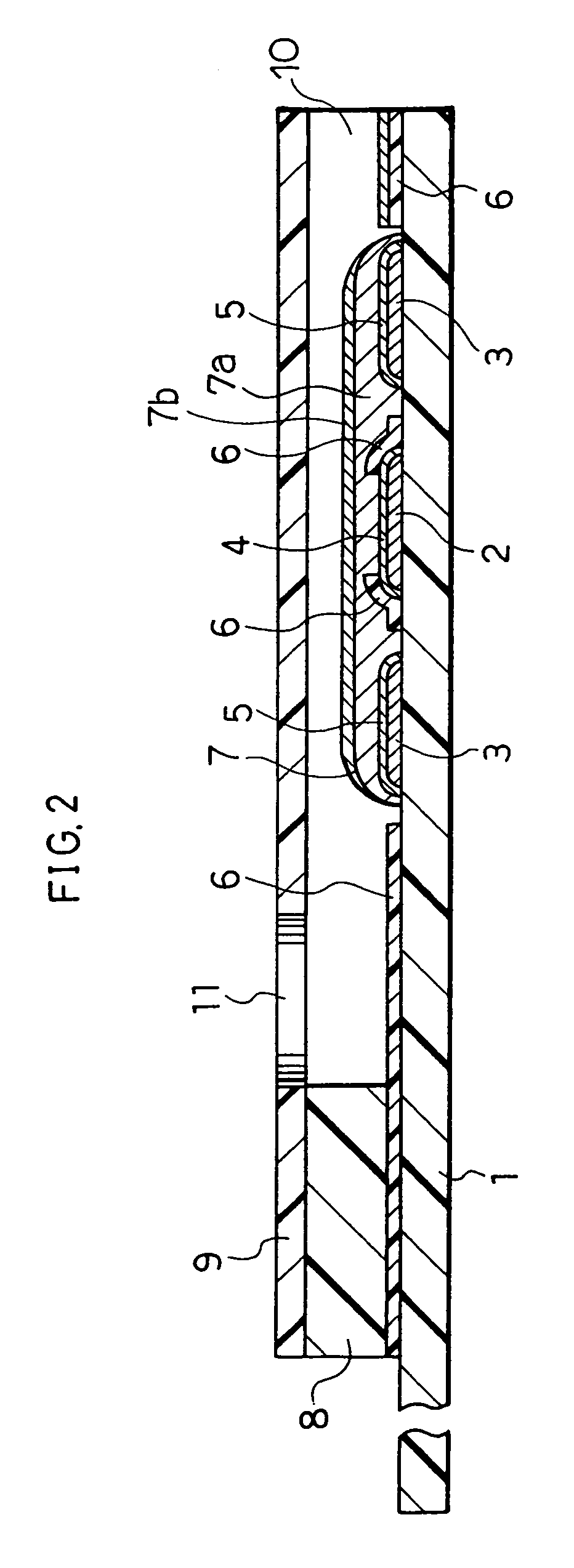
[0001]This application is the national stage under 35 U.S.C. 371 of PCT / JP00 / 06853, filed on Oct. 2, 2000.TECHNICAL FIELD[0002]The present invention relates to a glucose sensor capable of rapidly and simply quantifying a specific component in a sample with high accuracy. More specifically, the present invention relates to a glucose sensor using pyrrolo-quinoline quinone dependent glucose dehydrogenase.BACKGROUND ART[0003]Conventionally, a variety of biosensors have been proposed as a system for simply quantifying a specific component in a sample solution without diluting or stirring the sample solution. As one example of the biosensors, for instance, the following sensor has been known (Japanese Laid-Open Patent Publication No. Hei 2-062952).[0004]This biosensor is fabricated by forming an electrode system comprising a working electrode, a counter electrode and a reference electrode on an electrically insulating base plate by screen printing or other method and forming thereon an en...

Claims


Application Information

Patent Timeline
Patent Type & Authority Patents(United States)
IPC IPC(8): G01N27/327C12Q1/00G01N33/487
CPCC12Q1/006
Inventor WATANABE, MOTOKAZUYUGAWA, KEIKOYOSHIOKA, TOSHIHIKONANKAI, SHIRONAKAYAMA, JUNKOMIYAZAKI, SHOJIBABA, HIDEYUKI
Owner PHC HLDG CORP
Learn More