
Terbium or lutetium containing scintillator compositions having increased resistance to radiation damage

a technology of lutetium or lutetium, which is applied in the direction of radiation measurement, material analysis using wave/particle radiation, nuclear engineering, etc., can solve the problems of reducing image resolution, difficult to predict the change of any individual scintillator, and difficult to implement quantitative correction measures, so as to increase the resistance to radiation-induced changes in scintillator efficiency

Inactive Publication Date: 2006-03-07
GE MEDICAL SYST GLOBAL TECH CO LLC +1
View PDF28 Cites 24 Cited by
  • Summary
  • Abstract
  • Description
  • Claims
  • Application Information

AI Technical Summary

Benefits of technology

[0022]Scintillator materials and detectors of the present invention advantageously provide short decay time (to minimize scanning time), and that show reduced damage upon repeated exposure to the high energy radiation typically employed in the applications requiring scintillators (to increase the reproducibility of the measurements). Methods for scintillator preparation of the present invention are also reproducible, but simple enough to be cost-effective and easily adapted to existing protocols for scintillator manufacture.

Problems solved by technology

Radiation damage can lead to “ghost images” from prior scans which thereby reduce image resolution.
The change in light output that occurs upon radiation damage is often found to be variable in magnitude from batch-to-batch of the same scintillator, making it difficult to predict how any individual scintillator will change over time and thus, making it difficult to implement quantitative correction measures.
This amount of variation in light output which can occur as a result of x ray damage is undesirable in a quantitative x ray detector.

Method used


Image

  • Terbium or lutetium containing scintillator compositions having increased resistance to radiation damage
  • Terbium or lutetium containing scintillator compositions having increased resistance to radiation damage

Examples


example

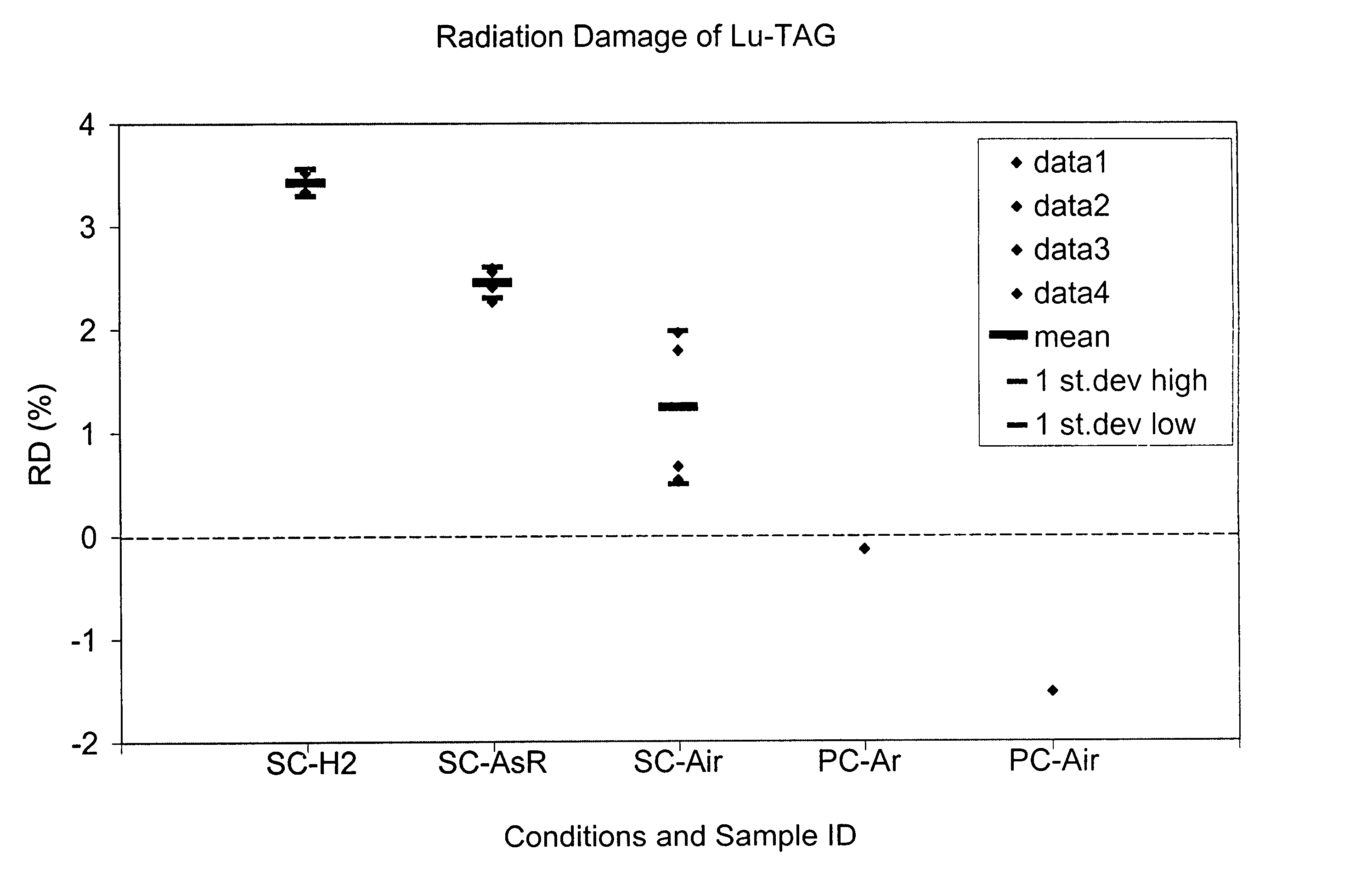
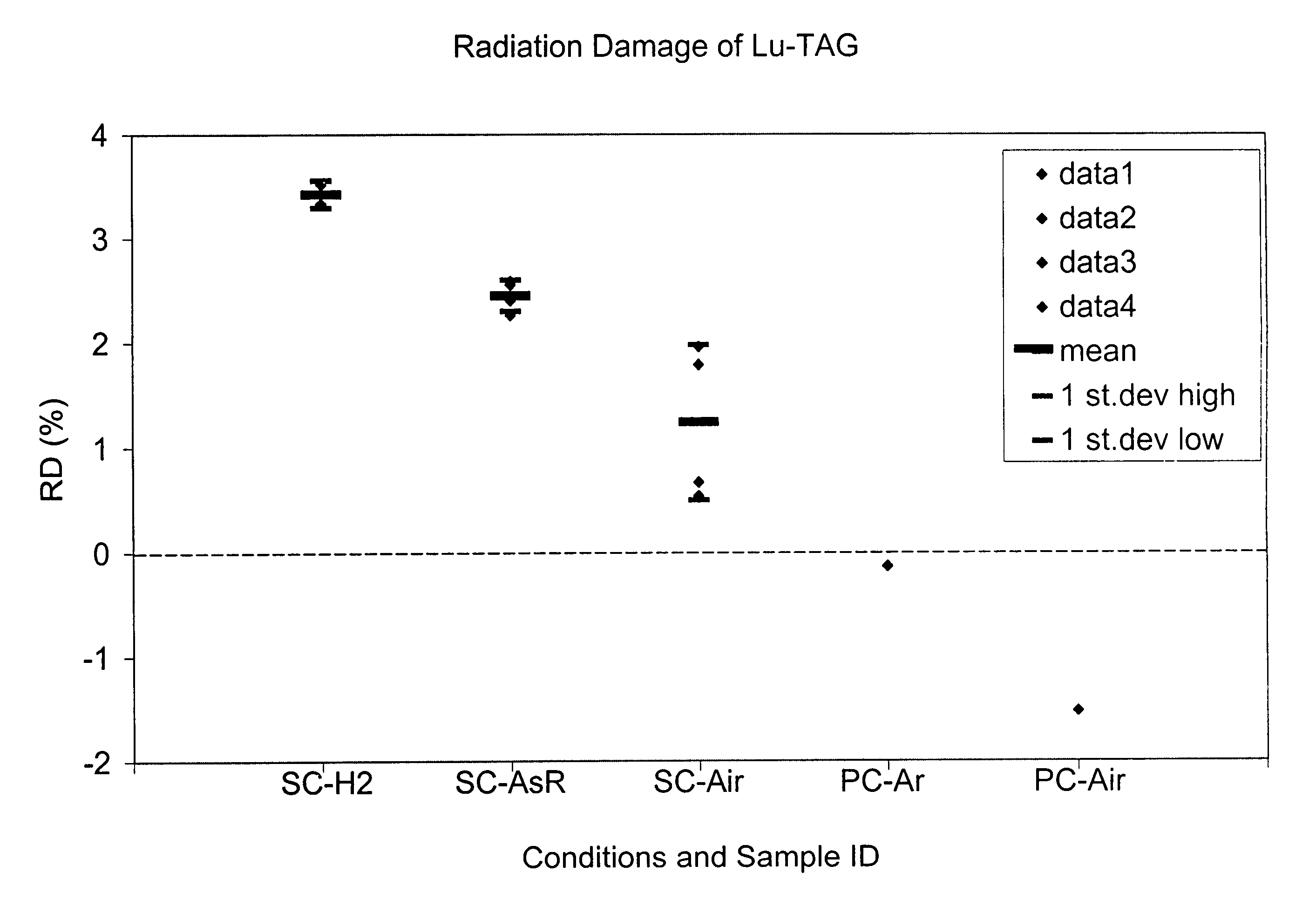
[0085]As shown in the FIG., radiation damage (% RD) from five different sets of samples that were either measured “As Received” or subjected to various conditions of annealing. All experiments used scintillators of Lu0.8Tb2.2Al5012 activated with Ce3+ ions.

[0086]Polycrystalline scintillator ceramic was prepared by sintering the garnet powder in a furnace at 1725° C. Single crystals were purchased commercially from Poly-Scientific (Northrop Grumman, N.C.). One method to prepare single crystals is by the Czochralski method, in which the elements are mixed in a crucible and then melted using low energy radio frequency induction or by resistance heating. A pull rod with a chuck containing a seed crystal at its lower end is then dipped into the crucible. The melt temperature is adjusted so that a meniscus is formed along the seed crystal. The pull rod is simultaneously rotated and lifted. Upon adjustment of power to the melt, a crystal is pulled from the melt.

[0087]To measure radiation-i...


PUM

PropertyMeasurementUnit
Fractionaaaaaaaaaa
Fractionaaaaaaaaaa
Fractionaaaaaaaaaa

Abstract

In some aspects, a scintillator composition includes, prior to annealing, the composition (G1-x-yAxREy)aDzO12, wherein D is selected from the group consisting of Al, Ga and In, G is selected from the group consisting of Tb, Y, La, Gd, and Yb, A is selected from the group consisting of Lu, Y, La, Gd, and Yb, and RE is selected from the group consisting of Ho, Er, Tm and Ce, and x is in the range from 0 up to about 0.2774, inclusive, y is in the range from about 0.001 up to about 0.012, inclusive, a is in the range 2.884 up to about 3.032, inclusive, and z is in the range from about 4.968 up to about 5.116, inclusive.

Description

CROSS REFERENCE TO RELATED APPLICATIONS[0001]This application is a continuation-in-part of U.S. application Ser. No. 10 / 316,151, filed Dec 10, 2002, published as U.S. Publication No. 20030127630 A1, and issued on Sep. 21, 2004 as U.S. Pat. No. 6,793,848, which is a continuation-in-part of U.S. application Ser. No. 09 / 682,737, filed Oct. 11, 2001, now U.S. Pat. No. 6,630,077 B2, issued Oct. 7, 2003. Priority is hereby claimed to both applications, which are incorporated by reference herein in their entirety.BACKGROUND OF THE INVENTION[0002]The present invention relates to terbium or lutetium containing scintillators that are activated with a rare earth metal ion, such as cerium, and treated by annealing at high temperatures in a defined oxygen atmosphere, such that the annealed scintillator has an increased resistance to high-energy radiation damage as compared to a same scintillator not treated by the methods of the present invention.[0003]Solid state scintillator materials have lon...

Claims


Application Information

Patent Timeline
IPC IPC(8): C09K11/08G01T1/20C04B35/50C09K11/00C09K11/77C09K11/78C09K11/80G01T1/202
CPCC09K11/7774C04B35/01C04B35/44C04B2235/3217C04B2235/3224C04B2235/9661C04B2235/3227C04B2235/3229C04B2235/3286C04B2235/6584C04B2235/764C04B2235/3225
Inventor VARTULI, JAMES SCOTTLYONS, ROBERT JOSEPH
Owner GE MEDICAL SYST GLOBAL TECH CO LLC
Learn More