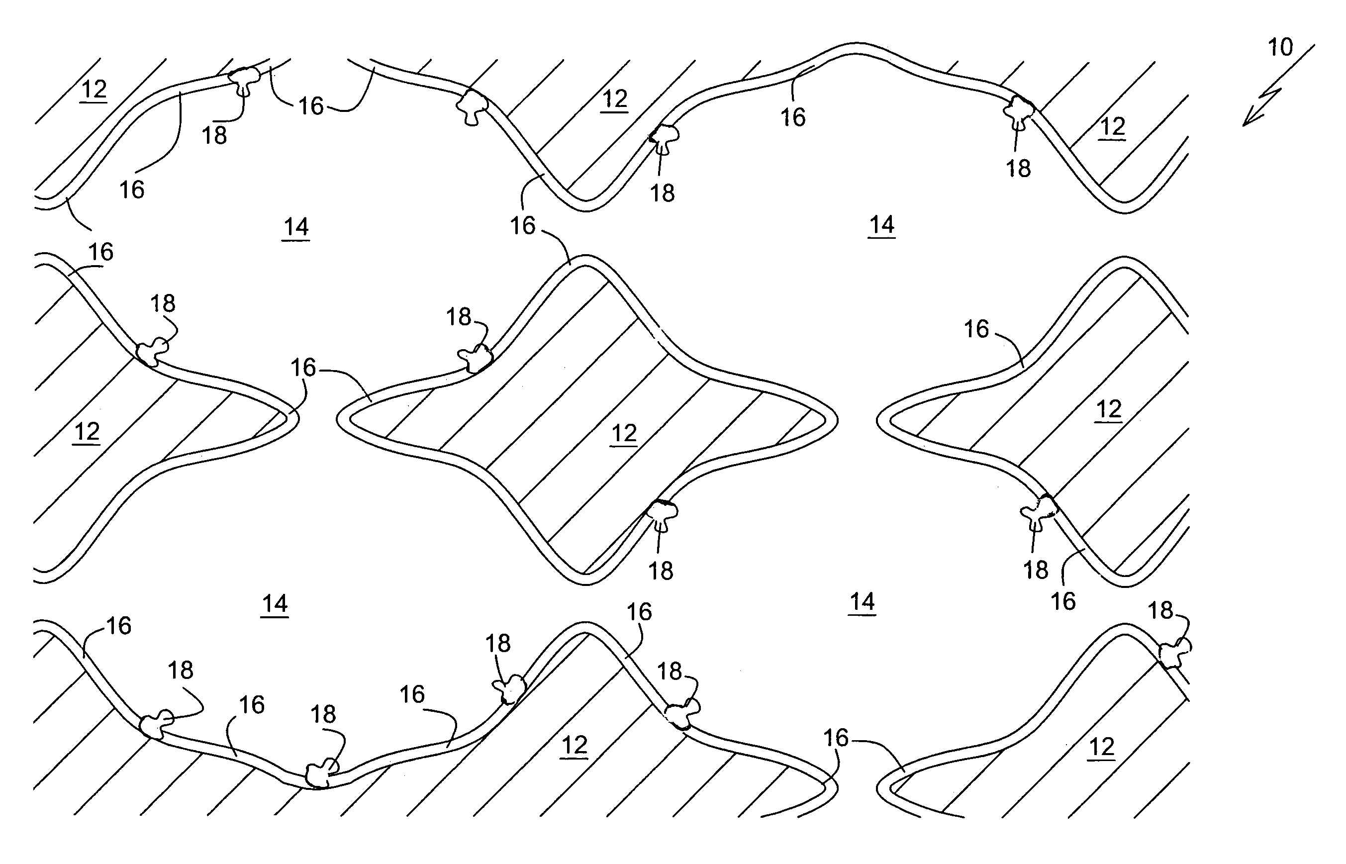
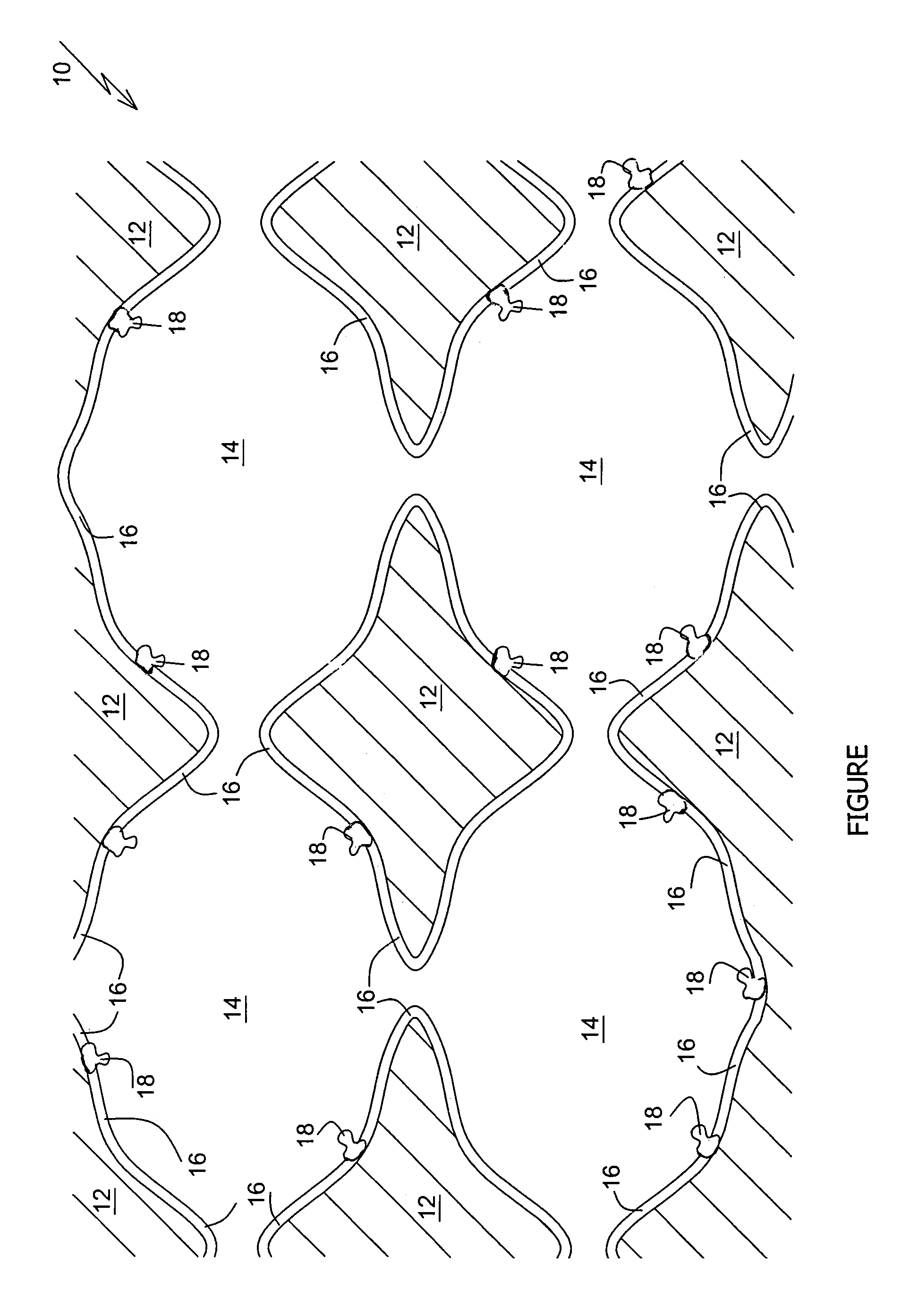
Flexible electroconductive foam, and method of preparation thereof

a flexible, electroconductive foam technology, applied in the direction of conductive materials, carbon-silicon compound conductors, organic conductors, etc., can solve the problems of degrading the structural and mechanical properties of foam, difficult to optimize the concentration of binder, and high cost of electrically conductive foams, so as to achieve the effect of swelling the matrix

Inactive Publication Date: 2006-03-07
MORE ENERGY
View PDF10 Cites 12 Cited by
  • Summary
  • Abstract
  • Description
  • Claims
  • Application Information

AI Technical Summary

Benefits of technology

[0012]Surprisingly, we have found that the swelling of the matrix by aromatic solvents can be largely mitigated by using a more concentrated dispersion: a dispersion that includes between about 10% and about 25% by weight of the electroconductive polymer and the organic dopant / dispersant, vs. less than 8% electroconductive polymer plus organic dopant / dispersant by weight in the prior art dispersion. In addition, the precursor foam, that is produced by introducing the dispersion into the pores of the matrix, is dried actively, for example in a convection dryer and / or in vacuum, rather than passively by just letting the precursor foam sit in ambient air as is common in the prior art.

Problems solved by technology

The problem with this method is that the amount of filler that must be included in the foam in order to obtain adequate electrical conductivity is sufficient to degrade the structural and mechanical properties of the foam relative to the structural and mechanical properties of the electrically insulating base foam.
When a metal is used as the electrically conductive material, the second method provides an electrically conductive foam with a low resistivity, possibly as low as 0.1 ohm-cm, and satisfactory mechanical properties; but such electrically conductive foams are very expensive.
One disadvantage of such electrically conductive foams is that it is difficult to optimize the binder concentration.
Low binder concentration gives poor particulate adhesion: the resulting foam tends to shed particles and so is unsuitable for some applications Another disadvantage of such electrically conductive foams is that a particulate concentration in excess of 30% often is needed to obtain adequate conductivity.
Such a high particulate concentration degrades the mechanical strength, flexibility and permeability of the foam.
In practice, however, the electrically conducting layers formed using dispersions of electroconductive polymers in water and in polar organic solvents such as alcohols tend to be discontinuous, so that the resulting electrically conductive foams have relatively high resistivities.

Method used


Image

  • Flexible electroconductive foam, and method of preparation thereof
  • Flexible electroconductive foam, and method of preparation thereof

Examples


example 1 (

Prior Art)

[0035]Electroconductive polymer: 9 g polyaniline.

[0036]Liquid medium: 9 ml 4.5% aqueous solution of polyvinyl alcohol. 132 ml water, 9 g dodecylbenzenesulfonic acid.

[0037]The polyaniline was dispersed in the liquid medium by milling in a ball mill for 4 hours at 400 rpm. The polyurethane foam was impregnated with the resulting dispersion by the “dip and nip” technique to produce a precursor foam. The precursor foam was dried in ambient air at room temperature for 30 minutes and then in a vacuum oven at 70° C. for one hour.

example 2

[0038]Electroconductive polymer: 7 g polyaniline.

[0039]Liquid medium: 70 ml m-xylene, 9 g dodecylbenzenesulfonic acid.

[0040]The polyaniline was dispersed in the xylene by milling in a ball mill for 1.5 hours at 400 rpm. The dodecylbenzenesulfonic acid was added to the dispersion and the dispersion was milled in the ball mill for another 1.5 hours at 400 rpm. The polyurethane foam was impregnated with the resulting dispersion by the “dip and nip” technique to produce a precursor foam. The precursor foam was dried in an ambient air airflow at room temperature for 30 minutes and then in a vacuum oven at 70° C. for 30 minutes.

example 3

[0041]Electroconductive polymer: 30 g polyaniline.

[0042]Particulate carbon: 18 g graphite flakes.

[0043]Liquid medium: 300 ml m-xylene, 30 g dodecylbenzenesulfonic acid.

[0044]The polyaniline was dispersed in 200 ml of the xylene by milling in a ball mill for 2.5 hours at 400 rpm. The dodecylbenzenesulfonic acid and the remaining 100 ml of the xylene were added to the dispersion and the dispersion was milled in the ball mill for another 1.5 hours at 400 rpm. The graphite was added to the dispersion and the dispersion was milled in the ball mill for another 4.5 hours at 400 rpm. The polyurethane foam was impregnated with the resulting dispersion by the “dip and nip” technique to produce a precursor foam. The precursor foam was dried in an ambient air airflow at room temperature for 30 minutes and then in a vacuum oven at 70° C. for 30 minutes.

[0045]The following table shows the % weight increase of the electroconductive foam over the base foam, and the resistivity of the electroconduct...


PUM

PropertyMeasurementUnit
temperatureaaaaaaaaaa
areaaaaaaaaaaa
electroconductiveaaaaaaaaaa

Abstract

A method of preparing an electroconductive foam, and the foam so prepared. An electroconductive polymer such as polyaniline is dispersed in a liquid medium that includes an aromatic solvent such as xylene and an organic dopant / dispersant such as an aromatic sulfonic acid. The electroconductive polymer together with the organic dopant / dispersant constitute between 10% and 25% of the resulting dispersion. The dispersion is introduced to the pores of an electrically insulating foam matrix such as polyurethane. Excess dispersion is expelled and the foam is dried actively, to line the pores with an electroconductive lining.

Description

FIELD AND BACKGROUND OF THE INVENTION[0001]The present invention is related to a method of preparing a flexible electroconductive foam, and the electroconductive foam so prepared.[0002]Flexible, electrically conducting foams are used as EMI (electromagnetic interference) shielding materials, electroconductive gaskets, gas sensors and electrostatic filters.[0003]Two methods are known in the art for preparing flexible, electrically conductive foams.[0004]In the first method, electrically conducting filler particles are mixed with the precursor of an otherwise electrically insulating polymer foam. The resulting foam is a combination of the electrically insulating polymer and the electrically conducting filler. Filler materials include particulate metals, particulate amorphous carbon, particulate graphite and particulate electroconductive polymers such as polypyrrole, polythiophene and polyaniline. The problem with this method is that the amount of filler that must be included in the fo...

Claims


Application Information

Patent Timeline
Patent Type & Authority Patents(United States)
IPC IPC(8): H01B1/20B05D5/12B32B1/00C08J9/42H01B1/12H01B1/24
CPCC08J9/42H01B1/128H01B1/24H01B1/124C08J2479/00Y10T428/25Y10T428/31551
Inventor OSHEROV, ALEXANDERSKLYARSKI, LEONIDGLANTS, ILYAKATSMAN, YURI
Owner MORE ENERGY
Why Eureka
Try Eureka