

Thermally switchable imageable elements containing betaine-containing co-polymers
a technology of co-polymer and imageable elements, which is applied in the field of imageable elements, can solve the problems of high cost of a substantial quantity of used developer, the cost of the developer, etc., and achieves the effect of reducing the cost of processing equipment, and reducing the cost of the process
- Summary
- Abstract
- Description
- Claims
- Application Information
AI Technical Summary
Benefits of technology
Problems solved by technology
Method used
Image

Examples
example 1
[0061]This example illustrates a general procedure for synthesis of the sulfobetaine-containing co-polymers. 0.2 g of AIBN, 5 g of MMA, 5.0 g of sulfobetaine monomer, 40 g of n-propanol, and 40 g of water were placed in a 150-ml 3-necked flask equipped with magnetic stirring, temperature controller and nitrogen inlet. The reaction mixture was stirred and heated at 60° C. under nitrogen for 6 hr. AIBN (0.1 g) was added and heating and stirring continued for an additional 16 hr. After the reaction mixture was cooled to room temperature, about 90 g of polymer solution was obtained. The polymers are shown in Table 1.
[0062]
TABLE 1Poly(sulfobetaine) copolymer listmonomers (wt %)Solvent (wt %)Sample IDMMASulfobetainen-PrwaterN.V. (%)initiatorPolymer 150(MOE) 50505011.2AIBNPolymer 270(MOE) 30505011.1AIBNPolymer 380(MOE) 20505010.8AIBNPolymer 460(MOE) 40505011.4AIBNPolymer 570(MNP) 30505010.8AIBNMMA = methyl methacrylateMOE = [2-(methacryloyloxy)ethyl]dimethyl-(3-sulfopropyl) ammonium hydrox...
example 2
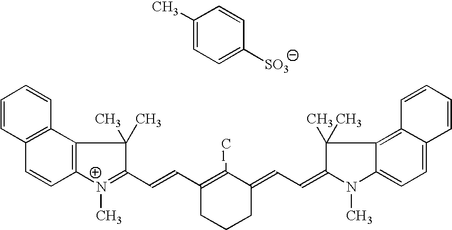
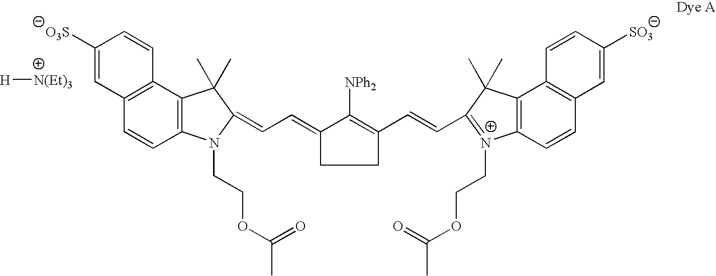
[0064]A coating solution was prepared by combining 2.68 g of Polymer 1 (from Example 1, Table 1), 0.019 g of Dye A, 0.05 g of 10% LODYNE® 103A, and 2.32 g of water. The coating solution was coated onto Substrate A using a wire wound bar. The resulting imageable element, consisting of the imageable layer on the substrate, was dried in a Ranar conveyor oven at about 76° C. for about one minute. The dry coating weight of the imageable layers was about 1.0 g / m2.
[0065]The resulting imageable element was placed on a CREO® Trendsetter 3244x imagesetter and imaged with 830 nm infrared laser radiation at a power of 12 W and a range of drum speeds from 210 to 50 rpm (corresponding to exposure energies ranging from 130 to 540 mJ / cm2). The imaged imageable element was treated with aqueous fountain solution that contained about 23.5 ml / L (3 oz per gallon) Varn Litho Etch142W (Varn International, Addison, Ill., USA), and about 23.5 mL (3 oz per gallon) Varn PAR (alcohol substitute) in water. A we...
example 3
[0066]A coating solution was prepared by combining 27.0 g of Polymer 2 (from Example 1, Table 1), 0.22 g of Dye A, 0.07 g of 10% LODYNE® 103A, and 22.7 g of water. Substrate B was mounted on a hot rotating drum. The substrate was then contacted with the coating solution, which was delivered to the substrate by a pump. The resulting imageable element, consisting of the imageable layer on the substrate, was dried by blowing hot air at 65° C. for about 2 minutes. The dry coating weight of the imageable layer was about 1.5 g / m2.
[0067]The imageable element was imaged as in Example 2 and the imaged imageable element treated with fountain solution and ink by rubbing ink and fountain solution on the imaged imageable element. The minimum exposure energy to achieve a good image was about 250 mJ / cm2.
[0068]A second imaged imageable element precursor, prepared similarly, was imaged at 400 mJ / cm2 and resulting printing plate mounted directly on an A. B. Dick duplicator press (A. B. Dick, Niles, I...
PUM
| Property | Measurement | Unit |
|---|---|---|
| thickness | aaaaa | aaaaa |
| optical density | aaaaa | aaaaa |
| optical density | aaaaa | aaaaa |
Abstract
Description
Claims
Application Information