
Dyes and use thereof in imaging members and methods

a technology of dyes and imaging members, applied in thermography, instruments, photosensitive materials, etc., can solve the problems of affecting the quality of the final image, the storage of the medium (before printing or in the form of the final image) may need to be for years, and the direct thermal system is still sensitive to hea

Active Publication Date: 2006-03-07
ZINK IMAGING
View PDF12 Cites 68 Cited by
  • Summary
  • Abstract
  • Description
  • Claims
  • Application Information

AI Technical Summary

Benefits of technology

"The present invention provides novel compounds that can be used as image dyes in imaging systems. These compounds have different colors when in crystalline form and in liquid form, making them useful in thermal imaging members. The compounds can be incorporated into thermal imaging members, which can be used in thermal imaging methods. The invention also provides methods for converting the crystalline form of the compounds to the liquid form by applying heat or a solvent. The compounds can be used in various imaging applications such as medical imaging, security imaging, and thermal imaging."

Problems solved by technology

On the other hand, unless a fixing step is incorporated, direct thermal systems are still sensitive to heat after thermal printing.
A problem arises in that the higher the temperature for coloration, the less sensitive the medium will be when printed with the thermal print head.
Storage of the medium (prior to printing or in the form of the final image) may need to be for years, however.
It may, for example, be required to perform a second thermal step, requiring a relatively long time of heating, after printing.
Nevertheless, in no case is there mentioned in this prior art any change in activation energy of the color-forming reaction that may occur when crystals of the compounds are melted.
Prior art systems in which at least two separate components are mixed following a melting transition suffer from the drawback that the temperature required to form an image in a very short time by a thermal print-head may be substantially higher than the temperature required to colorize the medium during longer periods of heating.
This difference is caused by the change in the rate of the diffusion needed to mix the molten components together, which may become limiting when heat is applied for very short periods.

Method used


Image

  • Dyes and use thereof in imaging members and methods
  • Dyes and use thereof in imaging members and methods

Examples


example 1

Synthesis of intermediates

Step 1A. Alkylation of 4-nitrocatechol

[0070]4-Nitrocatechol (23.26 g, 0.15 mol) and potassium carbonate (124.38 g, 0.9 mol) were placed in a one liter 3-neck flask fitted with a mechanical stirrer. Anhydrous dimethylformamide (350 mL) was added to this mixture followed by the addition to the suspension, dropwise, of 1-bromo octane (63.73 g, 0.33 mol). The reaction mixture was heated at 110° C. for 24 hours. The reaction was followed by TLC (2% methanol in methylene chloride). After the completion of the reaction the contents were cooled and poured dropwise with stirring into ice-water (1 L). The mixture was stirred for one hour and filtered. The collected solid was washed thoroughly with water, air-dried and then dried in vacuo at 30° C. This process produced brown crystals: (54.8 g, 0.144 mol, 96% yield). These crystals were used without further purification.

Step 1B. Synthesis of 3,4-dioctyloxyaniline

[0071]3,4-Dioctyloxynitrobenzene (25.25 g, 0.067 mol) wa...

example ii

Synthesis of Dye I

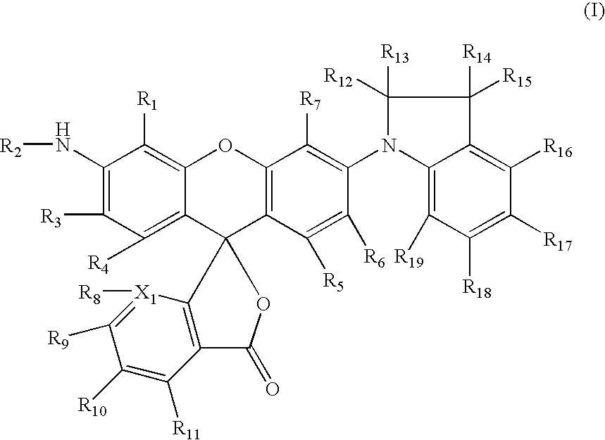
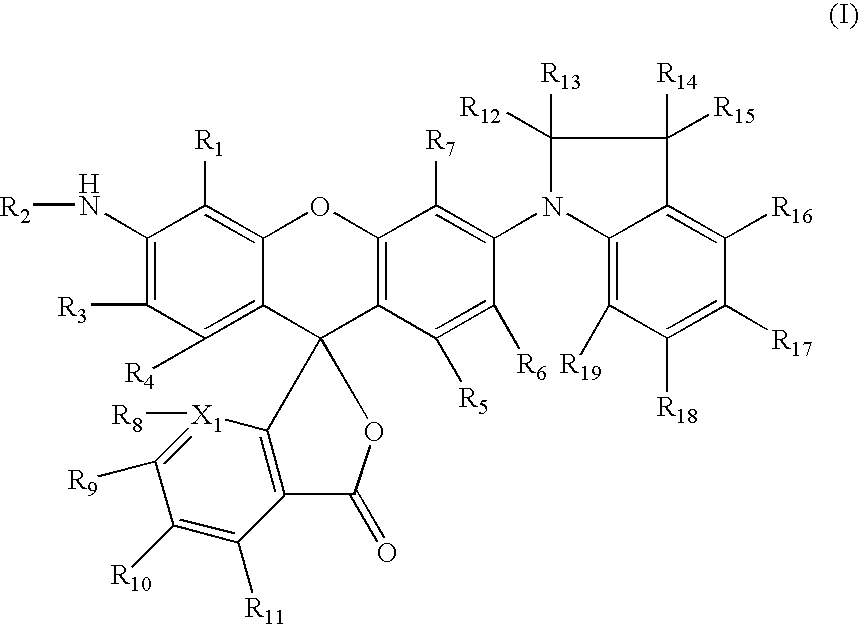
[0097]A mixture of hexachlorofluoran (2.0 g, 3.9 mmol), 2,3,3-trimethylindoline (0.9 g; 5.9 mmol), zinc chloride (1.6 g; 11.8 mmol), and zinc oxide (0.5 g; 5.9 mol) in sulfolane (6 g) was stirred with heating at 190° C. for 4 hours. To this mixture was added aniline (0.8 g; 7.9 mmol) and the mixture was then further stirred with heating at 160° C. for 14 hours. The mixture was cooled to 50° C. and quenched into 2N HCl (100 mL). The crude solid was isolated by filtration, washed with water several times and taken up in methylene chloride (150 mL). The methylene chloride solution was washed with sat. sodium bicarbonate (2×100 mL), dried over magnesium sulfate and the solvent removed. The residual solid was purified by column chromatography on silica gel (eluted with 30% ethyl acetate in hexane) to give 0.6 g pure product (22% yield) and then recrystallized from ca. 10% acetone in hexane to give colorless crystalline product, m.p. 210–215° C. (0.35 g, 13% yield).

[0098...

example iii

Synthesis of Dye II

[0099]A mixture of hexachlorofluoran (2.0 g, 3.9 mmol), indoline (0.7 g, 5.9 mmol), zinc chloride (1.6 g, 11.8 mmol), and zinc oxide (0.5 g, 5.9 mmol) in sulfolane (6 g) was stirred with heating at 145° C. for 90 minutes. To this mixture was added 4-(2-ethyl-1-hexyloxy) aniline (2.7 g, 7.9 mmol) and the mixture was further stirred with heating at 160° C. for 5 hours. The mixture was cooled to 50° C. and quenched into 2N HCl (100 mL). The crude solid was isolated by filtration, washed with water several times and taken up in methylene chloride (150 mL). The methylene chloride solution was washed with sat. sodium bicarbonate (2×100 mL), dried over magnesium sulfate and the solvent was evaporated. The residual solid was purified by column chromatography (10% ethyl acetate in methylene chloride) to give 1.2 g pure product (39% yield) and recrystallized from approximately 10% acetone / hexane to give colorless crystalline product (0.55 g, m.p. 180–182° C., 18% yield).

[01...


PUM

PropertyMeasurementUnit
melting temperaturesaaaaaaaaaa
temperaturesaaaaaaaaaa
melting temperaturesaaaaaaaaaa

Abstract

There are described novel rhodamine dye compounds and imaging members and imaging methods, including thermal imaging members and imaging methods, utilizing the compounds. The dye compounds exhibit a first color when in the crystalline form and a second color, different from the first color, when in the liquid, amorphous form.

Description

REFERENCE TO RELATED APPLICATIONS[0001]This application claims the benefit of provisional application Ser. No. 60 / 451,208, filed Feb. 28, 2003.[0002]This application is related to the following commonly assigned United States patent applications and patents, the disclosures of all of which are hereby incorporated by reference herein in their entirety:[0003]U.S. patent application Ser. No. 10 / 789,684, filed on even date herewith;[0004]U.S. Pat. No. 6,537,410 B2;[0005]U.S. patent application Ser. No. 10 / 151,432, filed May 20, 2002, (Unied States patent Application Publications No. US 2003 / 0125206 A1) now U.S. Pat. No. 6,801,233 B2; and[0006]U.S. Pat. No. 6,054,246.FIELD OF THE INVENTION[0007]This invention relates to novel compounds and, more particularly, to compounds which exhibit one color in the crystalline form and a second, different color in the liquid, or amorphous, form. Also described are imaging members and methods, including thermal imaging members and methods, utilizing t...

Claims


Application Information

Patent Timeline
Patent Type & Authority Patents(United States)
IPC IPC(8): G03C1/00C07D493/10G03C1/72G03C1/73B41M5/145B41M5/20B41M5/24B41M5/26B41M5/28B41M5/323B41M5/327B41M5/34B41M5/385C07D405/14C07D491/20C09B11/08C09B11/22C09B11/24C09B56/00C09B67/20
CPCB41M5/1455B41M5/284B41M5/3275B41M5/34B41M5/385C07D493/10C09B11/24C09B67/006C07D311/02Y10S430/145Y10S430/146B41M5/28B41M5/26
Inventor CHEON, KAP-SOOFILOSA, MICHAEL P.MARSHALL, JOHN L.
Owner ZINK IMAGING
Learn More