Soft switching converter using current shaping

a converter and current shaping technology, applied in the direction of ac-dc conversion, dctodc converters, dctodc inverters, etc., can solve the problems of reverse recovery losses and reverse recovery losses, and achieve the effect of reducing the negative impact of reverse recovery

Inactive Publication Date: 2006-03-07
DET INT HLDG LTD
View PDF7 Cites 14 Cited by
  • Summary
  • Abstract
  • Description
  • Claims
  • Application Information

AI Technical Summary

Benefits of technology

[0012]This invention relates to a circuit and method to reduce the negative impact of the reverse recovery in the rectifiers in a secondary or output circuit of a converter, while allowing zero voltage switching on the primary switching elements. This technique works by forcing the current carriers out of each output rectifier of a converter before a full reverse voltage from a transformer secondary is applied to it. This circuit and method of this invention operates by shaping the current through the output rectifiers using an additional injected or supplemental AC voltage superimposed on the main AC voltage induced in the secondary winding by the primary winding. In this implementation, even though the converter operates in continuous conduction mode, the reverse recovery losses in the rectifiers, like those discussed above with respect to the spikes 10 in FIG. 2B, are totally eliminated.
[0013]Another major advantage of the proposed circuit of a preferred embodiment implementing this invention is that the current reflected in the primary is shaped to a trapezoidal form with a low dI / dt during the turn on of the primary switches. This allows the completion of the resonant transition to zero voltage across the primary switching elements.
[0019]It will be seen that in accordance with the method of the invention a reverse bias voltage is applied to a semiconductor rectifier to deplete at least one semiconductor junction of carriers in advance of each application of a higher reverse biasing power transformer secondary voltage excursion. This avoids substantial reverse recovery losses. This is accomplished by applying an injection voltage waveform to the primary of a power transformer that couples an input or primary circuit to an output or a secondary circuit. Preferably the application of the injection voltage in accordance with the preferred method is by an auxiliary transformer having one winding connected to the primary of the power transformer and a second winding connected as described, i.e. through a capacitor to ground.
[0020]Of course in each of the methods, the object is to apply the lower reverse biasing voltage to each semiconductor rectifier or other semiconductor unidirectional current conducting devices in the secondary circuit so as to deplete the devices of carriers before a higher reverse biasing voltage is delivered to the device from the secondary of the power transformer to cause high reverse recovery losses. The depleted carriers are conducted by a secondary, conducting semiconductor rectifier.
[0021]The method of the preferred embodiment implementing the invention has the further advantage of adding an alternating current having a generally triangular waveform into the primary circuit to a set of semiconductor switching devices that make up a circuit that switches DC voltage to supply the power transformer primary. This current assures zero voltage switching by those switching devices.

Problems solved by technology

The depletion of carriers occurs prior to the application of the full reverse voltage across the device such as results in reverse recovery losses.
Both devices have applied to them the reverse biasing voltage that terminates forward conduction and depletes junction carriers prior to the application of a higher level of reverse voltage such as causes reverse recovery losses.

Method used


Image

  • Soft switching converter using current shaping
  • Soft switching converter using current shaping
  • Soft switching converter using current shaping

Examples


Embodiment Construction

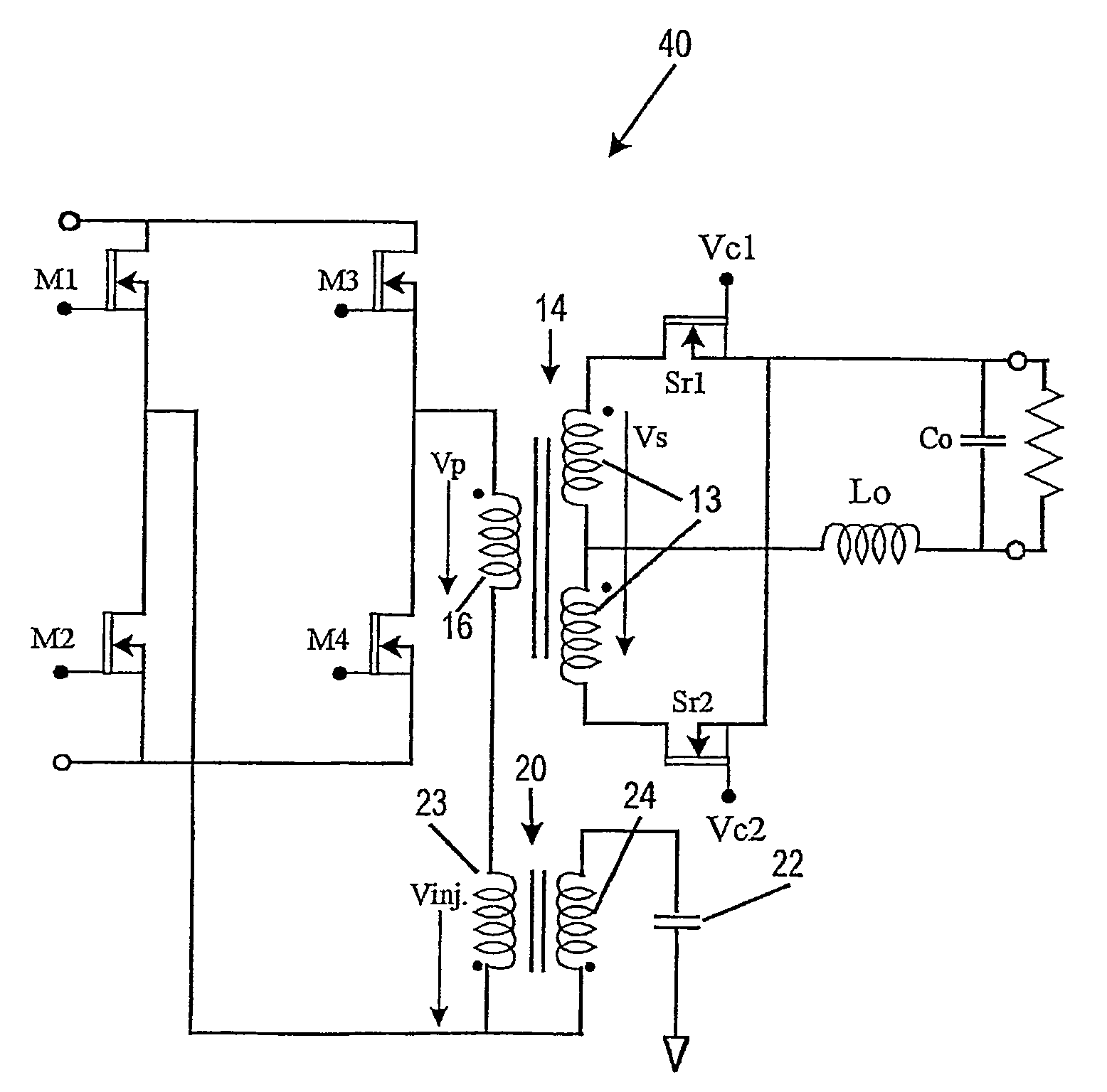
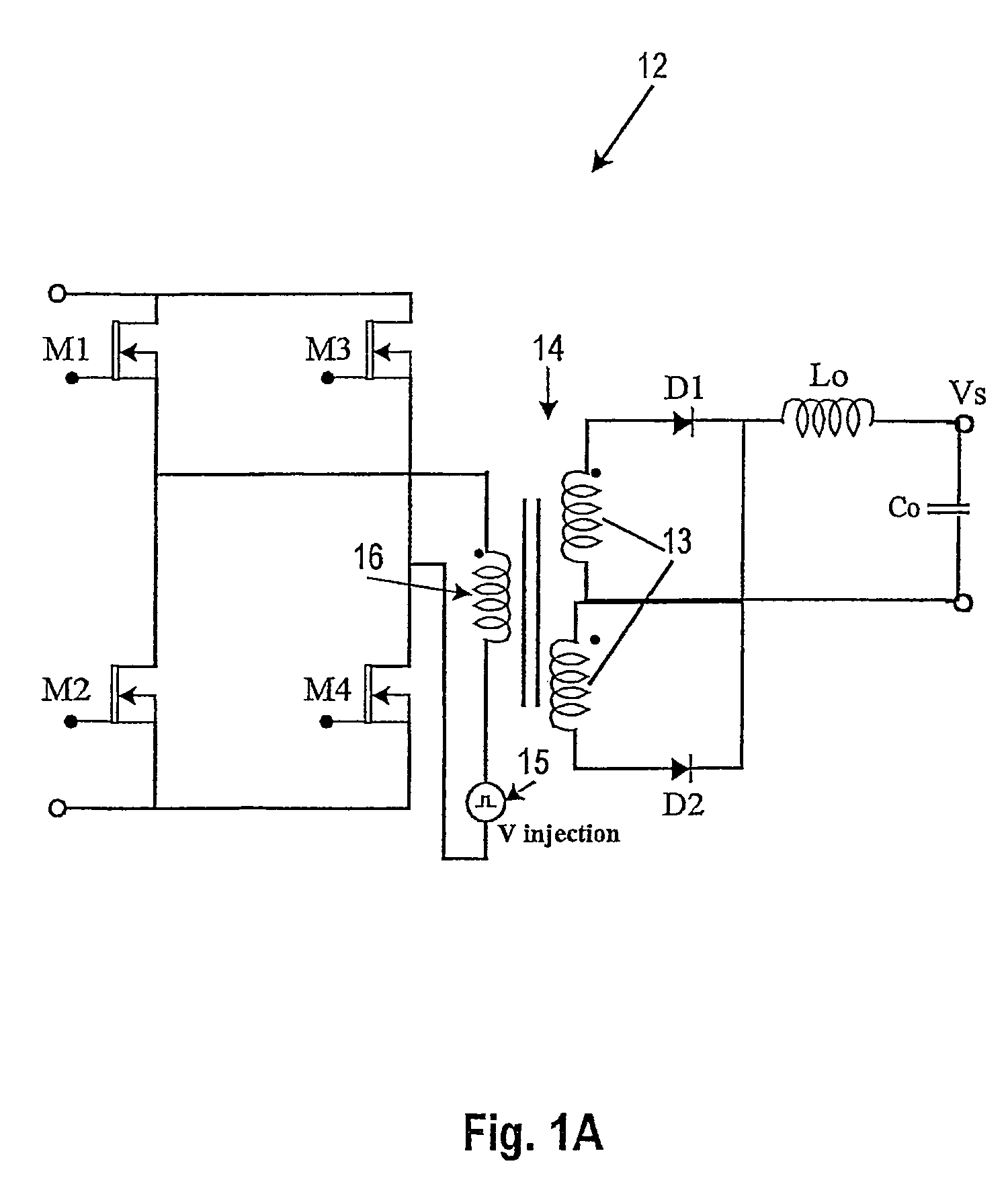
[0030]The present invention addresses the goal of eliminating the reverse recovery losses while maintaining continuous conduction mode in an output choke of a converter. The general concept is described in connection with FIG. 1A. It consists in adding an additional AC voltage source, which will generate a low voltage square waveform signal. FIG. 1A is a simplified schematic, and FIG. 1B illustrates key waveforms, both for the topology according to this invention. The circuit 12 of FIG. 1A is a typical full bridge, phase shifted topology, with an additional low voltage AC source 15 placed in series with a primary winding 16 of a power transformer 14.

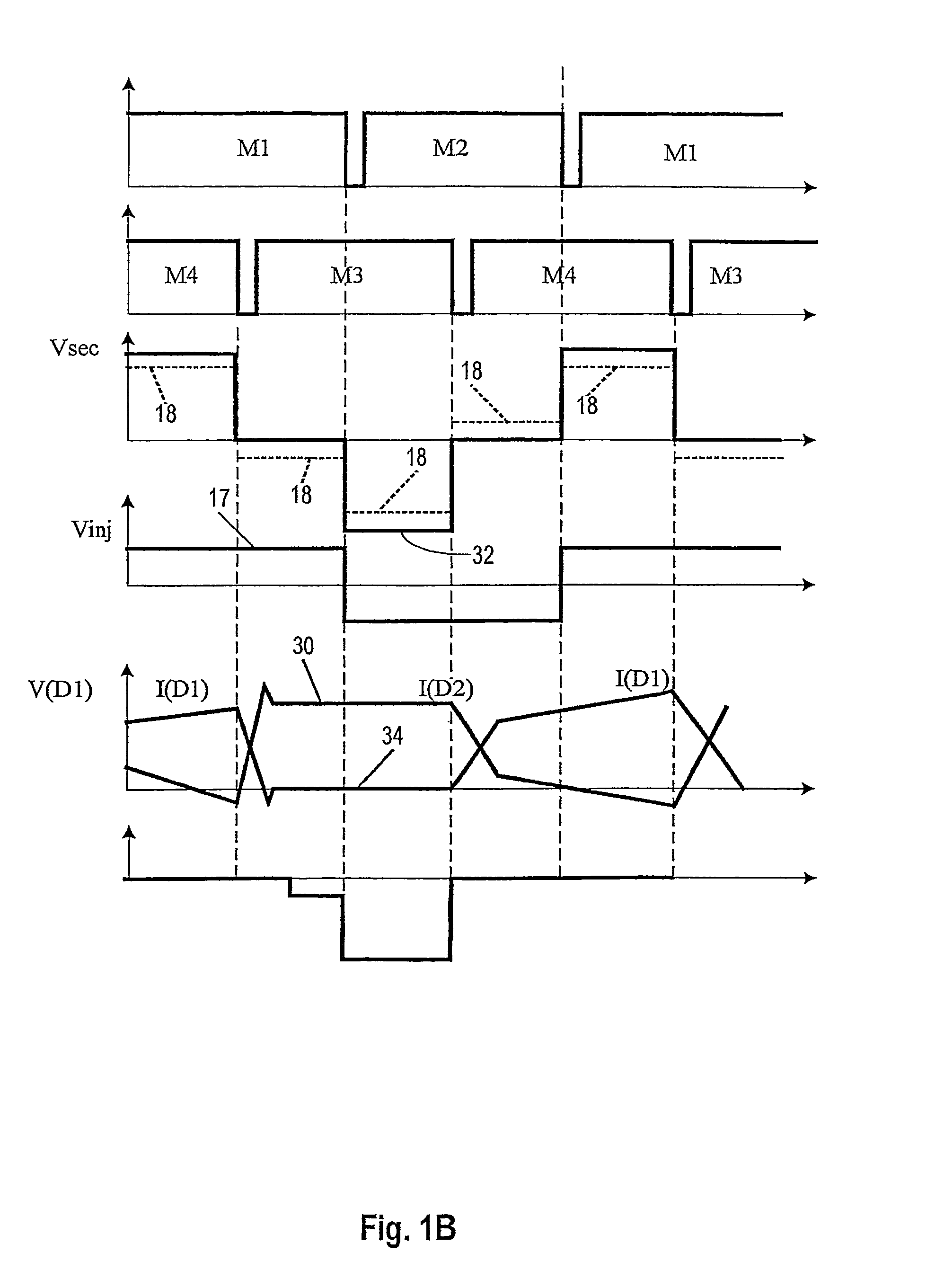
[0031]In FIG. 1B, the conventional control signals for the primary switching elements M1, M2, M3 and M4 are also depicted in the plots so labeled. The injected AC voltage, Vinj, will alter the voltage Vsec in the secondary 13 of the transformer as is depicted by the dotted lines 18 in FIG. 1B.

[0032]During the time wherein M1 and M4 are c...


PUM


Abstract

A converter topology that eliminates reverse recovery losses in its output rectifying semiconductor devices employs an AC injection voltage source in series with a power transformer primary winding. Input semiconductor switches in the converter's primary circuit are controlled to provide in the power transformer secondary a voltage across the winding or windings in a first direction forward biasing one of the output rectifying devices followed by a lower level reverse biasing voltage produced by the injection voltage. This lower level voltage across the secondary turns off the previously conducting rectifier device and drives carriers out of its semiconductor junction or junctions to eliminate reverse recovery losses occurring when the secondary applies a higher level reverse bias across the non-conducting rectifier device. The injection voltage source can be a transformer in addition to the power transformer having a primary winding in series with the primary winding of the power transformer and a secondary winding connected to ground through a capacitor. In addition to preventing reverse recovery losses in the rectifying devices in the secondary, the injection voltage transformer also injects an AC triangular waveform current into the current in the converter primary input circuit to the junction of the semiconductor switches where they are connected in a bridge circuit supplying the power transformer primary. By this, the injection voltage source assures zero voltage switching of the semiconductor switches even at light loads.

Description

CROSS REFERENCE TO RELATED APPLICATIONS[0001]Priority is claimed from U.S. provisional patent application Ser. No. 60 / 372,172 entitled “Soft Switching Converter Using Current Shaping” filed Apr. 12, 2002 in the name of Ionel D. Jitaru. That application is incorporated herein by reference.FIELD OF THE INVENTION[0002]This invention relates to DC-to-DC converters, DC-to-DC inverters and AC-to-DC converters (called generically herein “converters” or “power conversion circuits”), in which primary switching elements switches at zero voltage and secondary rectifiers have negligible reverse recovery losses.BACKGROUND OF THE INVENTION[0003]There is a continuing industry demand for converters of increasing power density, which means more power transferred in a given volume. A method for increasing the power transfer through a converter is to increase the switching frequency in order to minimize the size of the transformer and the capacitors. Using prior art topologies such as forward or flyba...

Claims


Application Information

Patent Timeline
Patent Type & Authority Patents(United States)
IPC IPC(8): H02M3/335H02M3/28H02M3/337
CPCH02M3/28H02M3/33592H02M3/337Y02B70/1491H02M2001/0048Y02B70/1475Y02B70/10H02M1/0048H02M3/33573
Inventor JITARU, IONEL D.
Owner DET INT HLDG LTD
Why Eureka
Try Eureka