Digital spread spectrum circuitry

a digital electronics and spread spectrum technology, applied in the direction of generating/distributing signals, pulse automatic control, angle demodulation by phase difference detection, etc., can solve the problems of digital systems malfunctioning, not capturing the data from the first, rising edges of clock signals in different parts of the system may not be synchronized, etc., to increase the frequency range and increase flexibility

Inactive Publication Date: 2006-03-07
XILINX INC
View PDF18 Cites 37 Cited by
  • Summary
  • Abstract
  • Description
  • Claims
  • Application Information

AI Technical Summary

Benefits of technology

[0019]The present invention provides a delay lock loop that synchronizes the reference clock signal with the skewed clock signal using a delay line having an initial propagation delay within a lock window. The lock window is a period of time between the minimum delay of the propagation delay and the maximum propagation delay. The extent of the lock window is chosen to ensure that changes in environmental conditions or clock frequenc

Problems solved by technology

However, due to various problems such as clock buffer delays, high capacitance of heavily loaded clock lines, and propagation delays, the rising edges of a clock signal in different parts of the system may not be synchronized.
Clock skew can cause digital systems to malfunction.
However, if the active edge on the second flip flop is delayed by clock skew, the second flip-flop might not capture the data from the first flip-flop before the first flip-flop changes state.
Although propagation delay DSKEW could be increased to any multiple of period P to achieve synchronization, most delay lock loops do not include a delay line capable of creatin

Method used


Image

  • Digital spread spectrum circuitry
  • Digital spread spectrum circuitry
  • Digital spread spectrum circuitry

Examples


Embodiment Construction

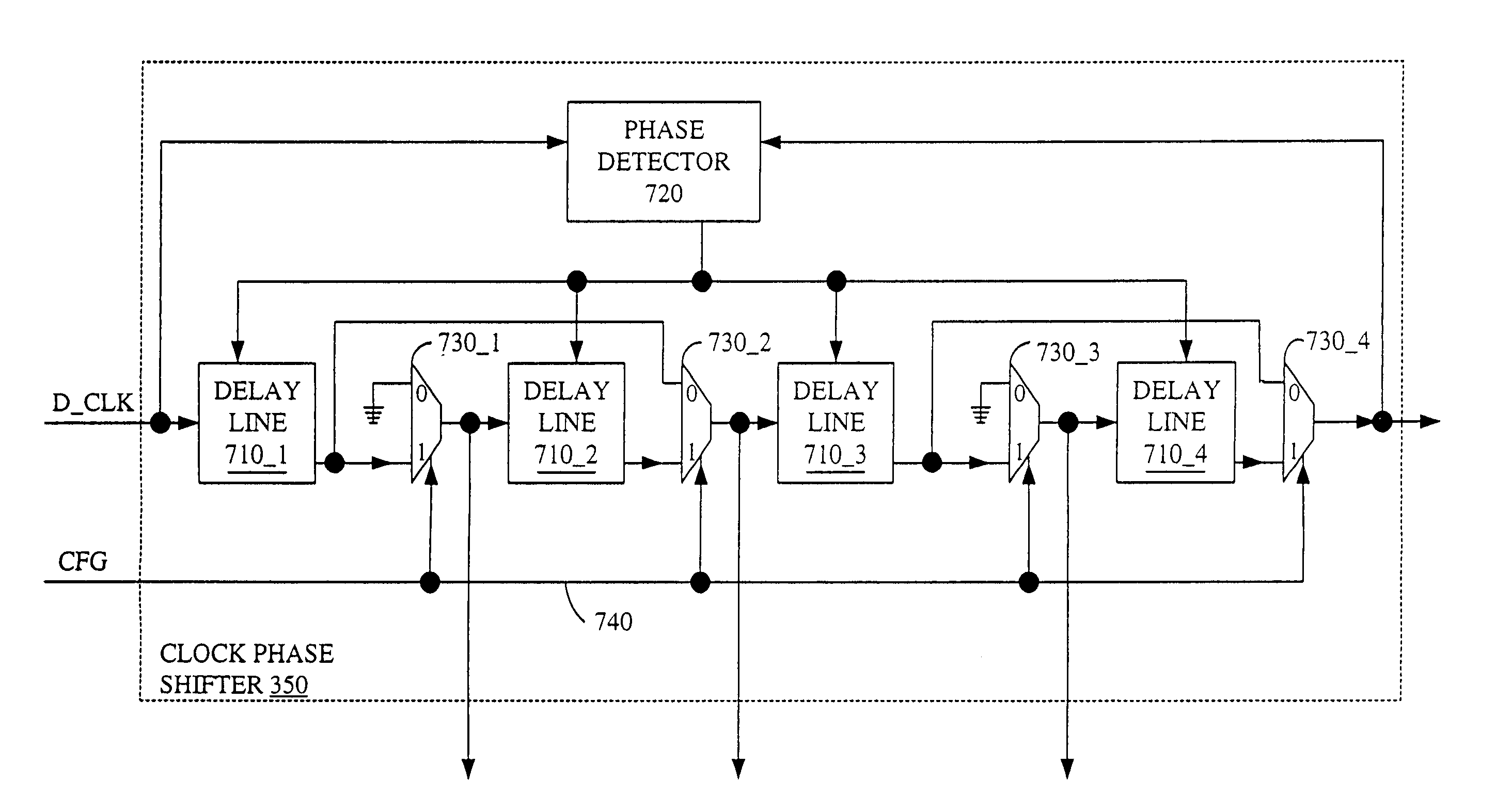
APPENDIX ACORRESPONDING TERMINOLOGY USED INTERMINOLOGYTHE SPECIFICATIONDLLDelay Lock Loop 400ZD2 sectionClock Phase Shifter 350PS sectionDigital Phase Shifter 1100ZD1 sectionDelay Line 310ResetZD2Reset Clock Phase Shifter 350ResetPSReset Digital Phase Shifter 1100ResetZD1Reset Delay Line 310ChangeZD2When asserted, allows Clock Phase Shifter 350 tomake a tap / trim changeGoPSGO (when asserted, allows Digital Phase Shifter tomake a tap / trim change)ChangeZD1When asserted, allows Delay Line 310 to make a tap / trim changeDLL_lockedDLL_LOCKEDlocked_preSimilar to DLL_LOCKED, except it remains trueeven if overflow occursPSlockedWhen asserted, indicates that the initial tap / trim fordelay line 1304 has been setFREEZEDLLUser signal that holds all updates to delay lines inDelay Lock Loop 400EnZD2Configuration bit that enables Clock Phase Shifter 350(allows ResetZD2 to go inactive)EnPSConfiguration bit that enables Digital Phase Shifter1100 (allows ResetPS to go inactive)EnZD1Configuration bit that...


PUM


Abstract

The frequency of a skew clock signal is dithered around a base frequency, thereby enabling this clock signal to comply with FCC requirements for electromagnetic emissions within a specified window. Delay is introduced such that the clock signals exhibits slightly different frequencies in successive periods. For example, the frequency of a 100 MHz clock signal can be adjusted to have frequencies of approximately 98, 98.5, 99, 99.5, 100, 100.5, 101, 101.5, and 102 MHz during different periods. Because the frequencies are spread in 0.5 MHz increments, only three frequencies are included in any 1 MHz window. As a result, ⅔ of the energy of the clock signal is not included when determining whether the clock signal meets the FCC electromagnetic emission requirements. By spreading the frequencies above and below the base frequency in a regular manner, the average frequency of the clock signal becomes equal to the base frequency.

Description

PRIORITY[0001]This is a continuation-in-part of U.S. patent application Ser. No. 09 / 102,740 filed Jun. 22, 1998, now U.S. Pat. No. 6,289,068 B1 issued on Sep. 11, 2001.CROSS-REFERENCE TO RELATED APPLICATIONS[0002]This application relates to commonly assigned U.S. Pat. No. 6,400,735 B1 which issued on Jun. 4, 2002, entitled “Glitchless Delay Line Using Gray Code Multiplexer”, which is incorporated herein by reference.FIELD OF THE INVENTION[0003]The present invention relates to delay lock loops (DLLs) for digital electronics. More specifically, the present invention relates to DLLs capable of locking clock signals over a wide frequency range.BACKGROUND OF THE INVENTION[0004]Synchronous digital systems, including board level systems and chip level systems, rely on one or more clock signals to synchronize elements across the system. Typically, one or more clock signals are distributed across the system on one or more clock lines. However, due to various problems such as clock buffer del...

Claims


Application Information

Patent Timeline
IPC IPC(8): H04B1/69H03D3/24H03L7/00H03L7/06G06F1/10H03K5/13H03L7/07H03L7/081
CPCG06F1/10H03L7/0814H03L7/07H03L7/0816
Inventor PERCEY, ANDREW K.LOGUE, JOHN D.GOETTING, F. ERICHHYLAND, PAUL G.
Owner XILINX INC
Why Eureka
Try Eureka