Linear RF power amplifier and transmitter

Inactive Publication Date: 2006-03-07
CADENCE DESIGN SYST INC
View PDF12 Cites 83 Cited by
  • Summary
  • Abstract
  • Description
  • Claims
  • Application Information

AI Technical Summary

Problems solved by technology

Although linear modulation schemes are more bandwidth efficient than constant envelope schemes, thus allowing more channels to be allocated within a given band, they are also more demanding of the linearity of the PA.
If a non-constant modulation envelope signal were to be applied as an input signal to a PA biased to such a point, the resulting output signal would be highly distorted due to the non-linear characteristic.
This distortion would lead to spreading of the PA output spectrum into the adjacent channels, therefore effectively negating any gains from the bandwidth efficiency of the linear modulation schemes.
Another resulting problem of “backing off” the output PA is the increased power dissipation in each of the output devices which increases both the cost and the difficulty of integrating transmitter circuitry into an integrated circuit.
This has the effect of raising efficiency but requires the use of power hybrid combiner and delay lines which cannot be integrated onto silicon and also contribute to power loss.
Furthermore, such a system relies on cancellation and therefore is prone to drift, and must be corrected adaptively.
However, care has to be taken to avoid spurious problems in an integrated transmitter, extra complication is introduced by adding more local oscillators, and the presence of discrete narrowband tones may create an interference problems in wideband communications channels.
Another drawback is the increased alignment and test time which will increase cost over an equivalent constant envelope transmitter.
An envelope feedback linear transmitter as in the described prior art has one advantage that almost all of the functional blocks can be incorporated into an integrated circuit (IC). there are, however, a number of disadvantages of such an arrangement, particularly when high modulation rates are required, wherein the arrangement becomes particularly unsuitable.
Furthermore, the system requirements for an envelope feedback linear transmitter which could work with high modulation rates are harsh.
A number of the disadvantages together with explanations of the requirements for operation at a high modulation rate are given below:1) In order to operate effectively with high modulation rates, a closed loop amplitude control around the envelope detector would be required with a very fast response time.2) The fractional-N phase locked loop (PLL) would have to cope with very high speed phase reversals in the modulation.3) There is no facility for controlling time slippage between the AM and PM modulation means.4) The use of a large divider in the PLL would result in adjacent channel interference due to synthesizer phase noise and hence will increase the likelihood of spurious signal generation.
The problems with this technique are that extra processing is required to keep the two signals coherent, and extra local oscillators are required.
Furthermore, there is also a risk of introducing unwanted signals at the transmitter output by the downconverter, and extra A / Ds are required for a full duplex system.

Method used


Image

  • Linear RF power amplifier and transmitter
  • Linear RF power amplifier and transmitter
  • Linear RF power amplifier and transmitter

Examples


Embodiment Construction

:

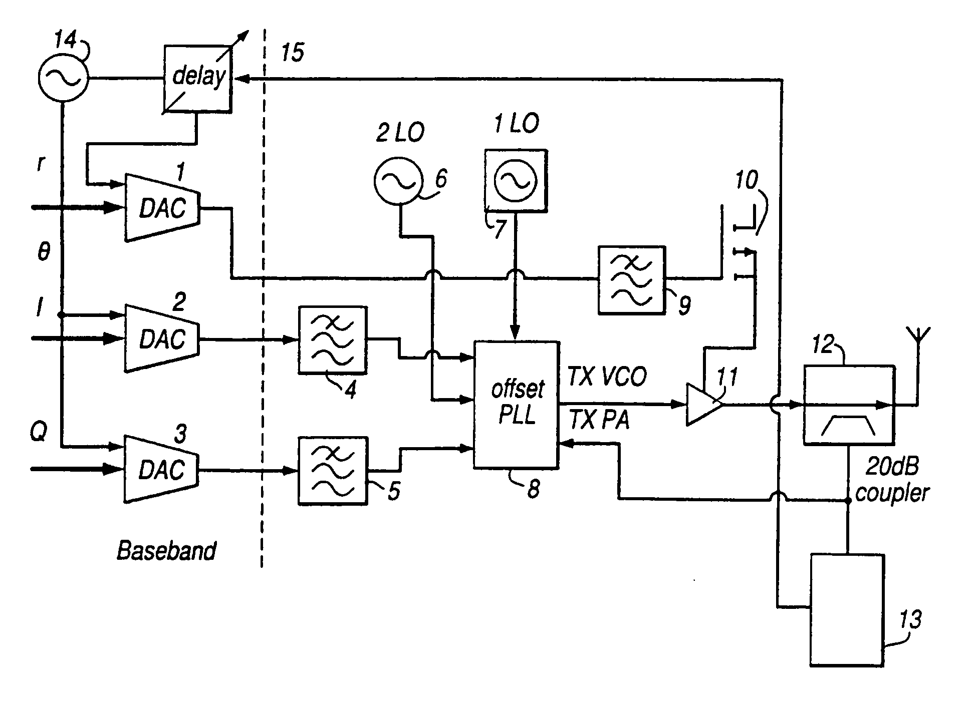
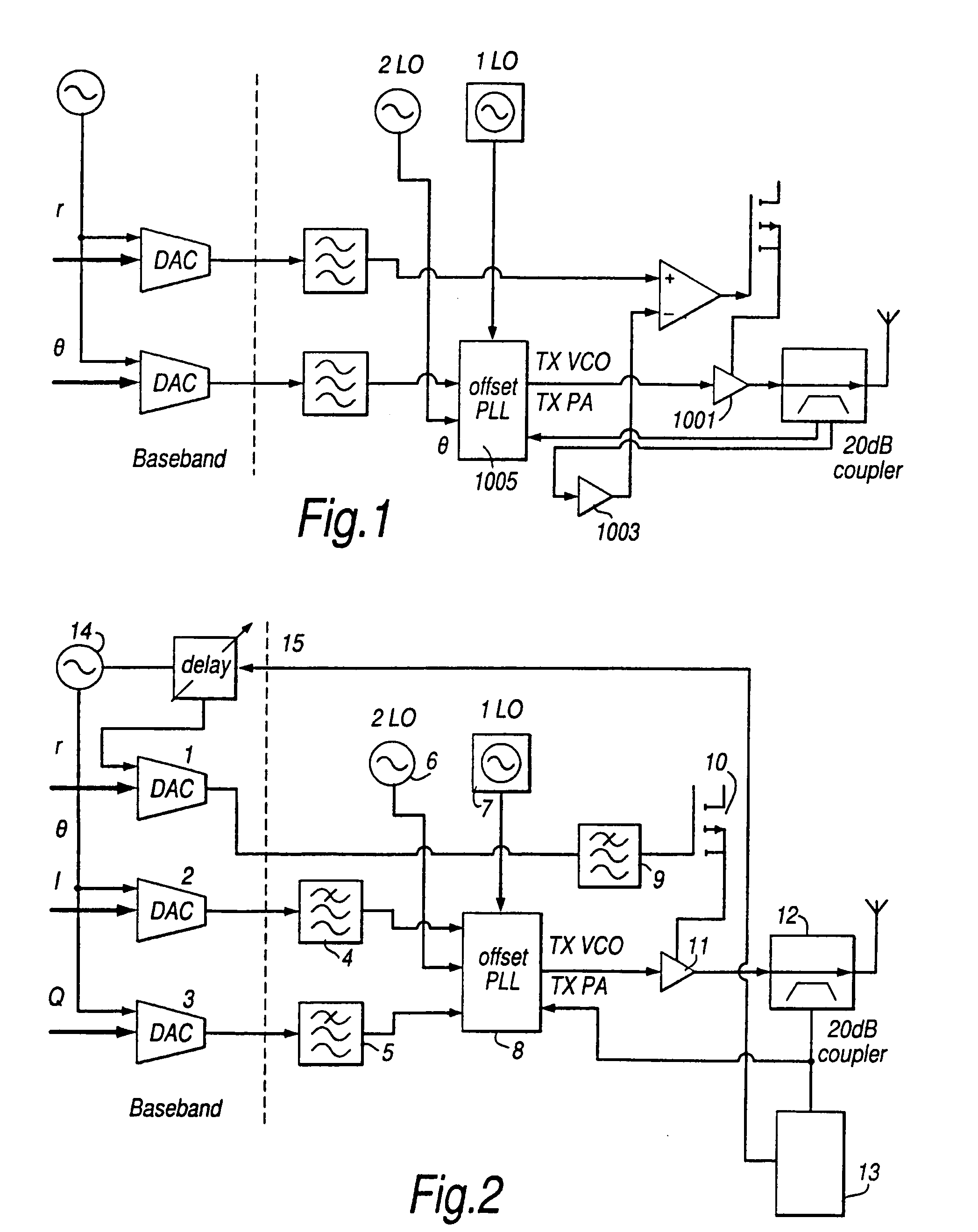
[0044]With reference to FIG. 2, a first preferred embodiment of the present invention will now be described.

[0045]FIG. 2 shows a block diagram of a linear PA and transmitter arrangement according to the present invention. The baseband processor of the transmitter resolves the signal into amplitude (r) and phase components (8). The phase component (8) is then further resolved into its in phase (I) and quadrature (Q components, wherein:

I=cos (θ); and

Q=sin (θ).

[0046]The resolution of the input signal into its amplitude r and

[0047]In-phase and quadrature components I and Q takes place at baseband before upconversion.

[0048]The baseband output is connected to DACs 1, 2 and 3 DAC 1 converts the amplitude representation of the signal, whereas DACs 2 and 3 are used to provide a phase representation of the signal. The DACs are provided with a clock signal from an oscillator 14. The respective I and Q signals output from the DACs are then interpolated with filters 4 and 5 and subsequently use...


PUM


Abstract

A transmitter circuit means is arranged to provide linear amplification of non-constant envelope modulated RF signals by directly amplitude modulating the transmitter power amplifier with the amplitude component of the baseband signal. In addition, the signal to be transmitted is phase modulated by the In-phase and quadrature components of the baseband signal, and synchronization means arc provided in order to correct any time slippage between the directly applied amplitude modulation and the phase modulation. The modulation synchronisation correction contributes significantly to the linearity of the transmitter.

Description

BACKGROUND OF THE INVENTION:[0001]The present invention provides a linear radio frequency (RF) power amplifier which is particularly suited for amplifying a linearly modulated signal.[0002]More particularly, the present invention provides a linear RF power amplifier and transmitter in which the polar components of the input signal are manipulated at baseband in order to correct for any non-linearities introduced within the amplifier and hence provide for increased power amplifier (PA) efficiency.[0003]PA efficiency is a vital parameter in portable radio equipment as it directly affects talk time. Linear modulation schemes, such as QPSK or DQPSK are characterized by having a non-constant amplitude envelope, as opposed to FSK or GMSK schemes which are constant envelope. Although linear modulation schemes are more bandwidth efficient than constant envelope schemes, thus allowing more channels to be allocated within a given band, they are also more demanding of the linearity of the PA. ...

Claims


Application Information

Patent Timeline
Patent Type & Authority Patents(United States)
IPC IPC(8): H04B1/04H03F1/32H03L7/08H04L27/20
CPCH04L27/2071H04L27/2046H04B2001/0441H03F1/3223H03F3/24
Inventor WILSON, MARTIN PAUL
Owner CADENCE DESIGN SYST INC
Why Eureka
Try Eureka