
Fuser member, apparatus and method for electrostatographic reproduction

a fuser and electrostatographic technology, applied in the field of electrostatographic imaging and recording apparatus, can solve the problems of increasing toner offset, interfering with the operation of the electrostatographic apparatus and the quality of the final product of the electrostatographic process, and increasing the contamination of the fuser member, so as to achieve good paper handling, good dimensional stability, and high viscosity

Active Publication Date: 2006-03-21
EASTMAN KODAK CO +1
View PDF64 Cites 14 Cited by
  • Summary
  • Abstract
  • Description
  • Claims
  • Application Information

AI Technical Summary

Benefits of technology

[0044]The fuser roller further provides good paper handling when the roller comprises either a “crown” shaped profile, i.e., the finished roller has a center portion (the location on the roller which is half the overall length of the roller, as measured from one of its ends) wherein the diameter of the roller is greater than the diameter at the ends of the roller; or a “flare” shaped profile, i.e., the ends of the roller have a diameter which is greater than the diameter at the center portion of the roller. In more preferred embodiments, the difference in diameters at the center portion of the roller and ends of the roller can vary from between about −2 to about +4 mils, as further described hereinafter.
[0045]The fuser roller further provides good dimensional stability when used in conjunction with high viscosity release fluids where the viscosity is greater than 1,000 centistokes (cSt). The fuser roller further provides good dimensional stability when the cushion exhibits less than 36% swell in toluene.
[0046]By use of a fuser member or fusing apparatus according to the present invention, it has been discovered that fusing quality is maintained even where the quantity of heat conducting filler in the fusing surface layer is reduced, especially when fusing is accomplished using external heat. Accordingly, the present invention has an advantage of allowing for a reduction of the heat conductive filler content of the fusing surface layer, thereby lessening toner contamination, while also improving wear resistance and providing effective fusing of toner to receiver.
[0047]It has further been discovered that in a toner fusing system which utilizes external heating as its primary heat source, and which also utilizes a fuser member with one or more base cushion layers and soft fusing surface layer according to the invention, the thickness and durometer hardness of the cushion and fusing surface layer are important to operation of the system. Specifically, these features have been found to be important to minimizing contamination of the surface layer, and also to providing a fuser member with sufficient strength, wearability, and resistance of such layers to delamination.
[0048]In this regard, by keeping the fusing surface layer within a particular durometer hardness range and also maintaining the base cushion within a certain durometer hardness range, there is significantly less wear during operation of the system while maintaining a desired fusing nip and paper handling characteristics. Surprisingly, the degree of attachment of the toner to the receiver or other substrate is not affected by the thermal conductivity of the surface layer as a whole, by the amount of heat conducting particles therein, by the identity of these particles, or by the degree of thermal conductivity characterizing the particular type of heat conducting particles employed. Still further, it has been discovered that keeping the overall cushion layer (the base cushion and surface layer) within a particular range for its apparent, i.e., composite, hardness, the advantages of the relatively soft surface layer can be obtained without adversely impacting the performance of the fuser roller.

Problems solved by technology

Toner on the fusing member therefore can interfere with the operation of the electrostatographic apparatus and with the quality of the ultimate product of the electrostatographic process.
Therefore, increasing the amount of heat conducting filler content in the fusing surface layer, by providing more reactive sites for the toner, can increase toner offset and therefore also increase contamination of the fuser member.

Method used


Image

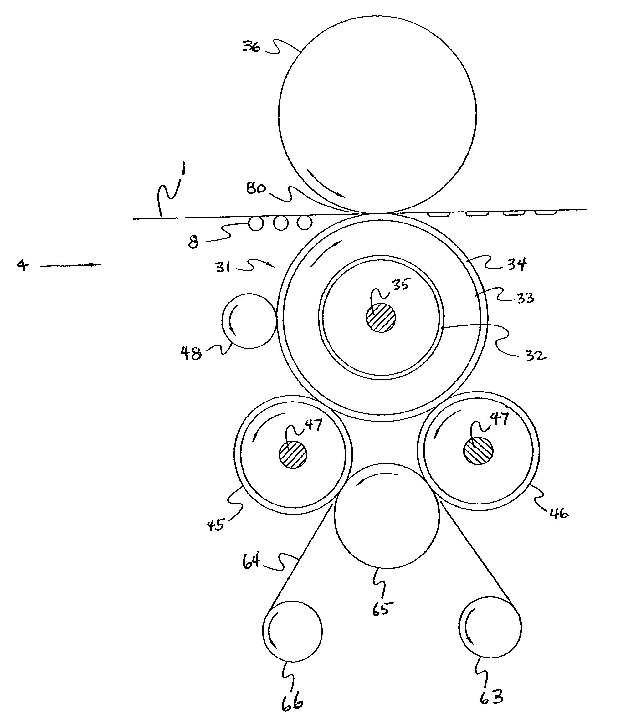
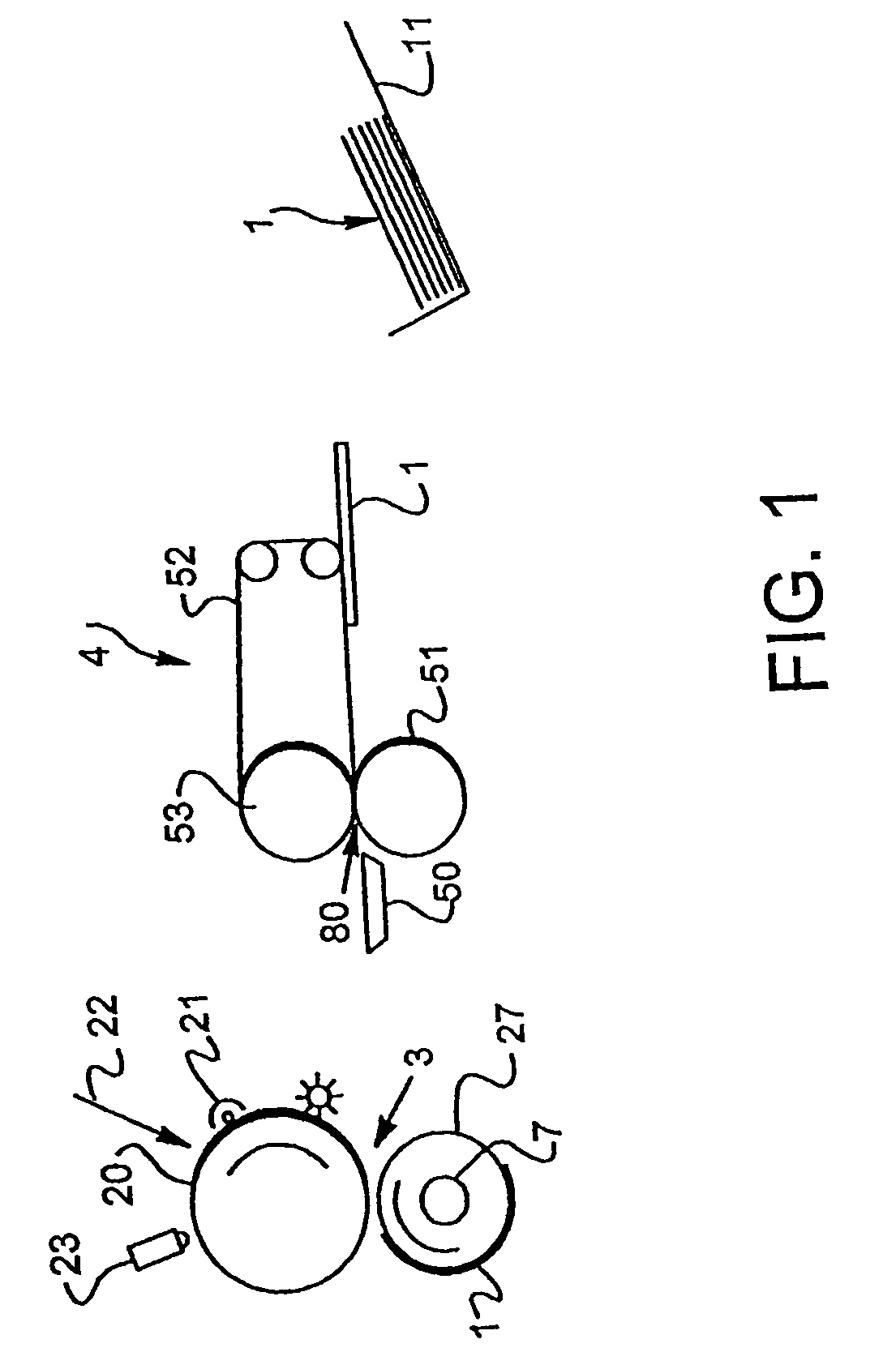
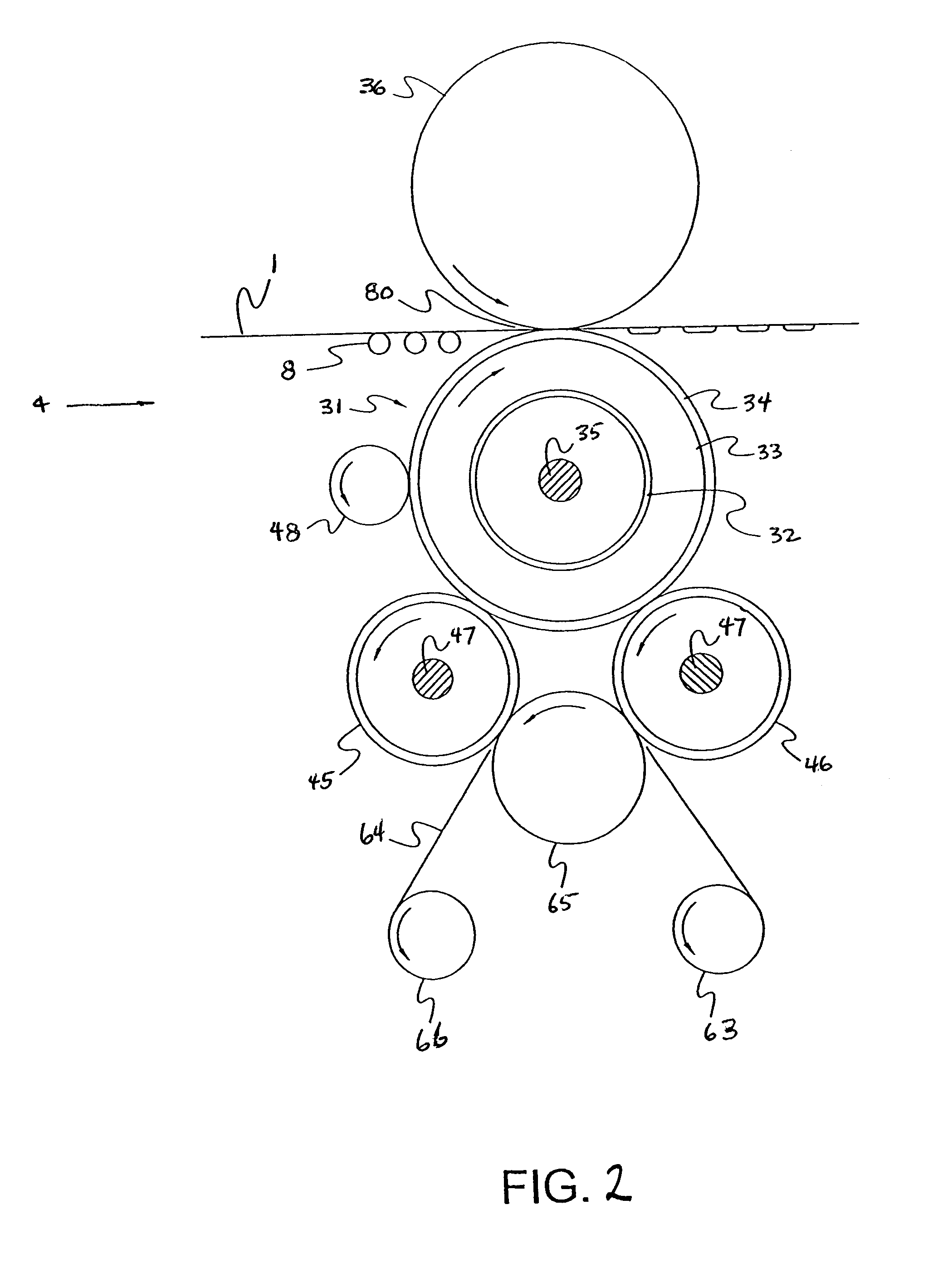
  • Fuser member, apparatus and method for electrostatographic reproduction
  • Fuser member, apparatus and method for electrostatographic reproduction
  • Fuser member, apparatus and method for electrostatographic reproduction

Examples


example 1

[0176]Example 1 is prepared by substantially repeating the procedure of Comparative Example A, except as provided otherwise hereinafter. Initially, a mixture is formed by combining 78.9 parts of polydimethylsiloxane (LS4340-103) per 100 parts of the mixture obtained by Comparative Example A (the polydimethylsiloxane and AL602 alumina powder mixture) prior to adding Cat 50 catalyst. Cat 50 is then added at 0.45 parts per 100 parts of the mixture, and then the mixture is degassed, injection molded, and cured substantially as in Comparative Example A to obtain a slab. The slab is post cured, sampled, and tested substantially as described in Comparative Example A, with the data being given in Table I for comparison purposes. Relative to Comparative Example A, the resulting slab has a reduced amount of filler in terms of volume percent, with a corresponding reduction in durometer hardness.

example 2

[0177]Example 2 is prepared by substantially repeating the procedure of Example 1, except as provided otherwise hereinafter. Initially, a mixture is formed by combining 27.6 parts of polydimethylsiloxane (LS4340-103) per 100 parts of the mixture obtained by Comparative Example B (polydimethylsiloxane and AL601 alumina powder mixture) prior to adding Cat 50 catalyst. Cat 50 is then added at 0.36 parts per 100 parts of the mixture before degassing, injection molding, and curing the mixture substantially as described in Comparative Example A to obtain a slab. The slab is post cured, sampled, and tested substantially as described in Comparative Example A, with the data being given in Table I for comparison purposes. Relative to Comparative Example B, the resulting slab has a reduced amount of filler in terms of volume percent, with a corresponding reduction in durometer hardness.

example 3

[0178]The procedure of Comparative Example A is substantially repeated, except as provided otherwise hereinafter. A mixture is initially formed by combining 70 parts of polydimethylsiloxane (LS4340-103) per 100 parts of the mixture prepared in Comparative Example D (the polydimethylsiloxane and AL600 alumina powder) by hand mixing and compounding in the three roll mill. The mixture is combined with 0.25 parts of Catalyst 50 per 100 parts of mixture before degassing, then the resulting mixture is injection molded and cured substantially as described in Comparative Example A to obtain a slab. The slab is post cured, sampled, and tested substantially as described in Comparative Example A. The data for the slab prepared according to Example 3 is shown in Table I.

[0179]

TABLE IExamples 1–3 and Comparative Examples A–D - Slab Sample DataParticle Size (μm)Larger thanTotalAlumina95% of99% ofFiller1FillerDurometerMeanthethe95 weightWear RateContentContenthardness2Fillernumber ofnumber ofperce...


PUM


Abstract

Disclosed is a fuser member, including fusing apparatus and electrostatographic methods which employ the fuser member, which has improved wear resistance and a reduced tendency to contaminate with toner particles. The fuser member comprises a core and a pliant coating thereon. The coating comprises a base cushion layer comprised of a first elastomeric composition, with a surface layer thereover comprised of a second elastomeric composition. The hardness of the surface layer is equal to or less than the hardness of the base cushion layer. In embodiments, the surface layer further comprises a particulate silica filler in an amount of about 10 volume percent or less, based on total volume of the surface layer.

Description

REFERENCE TO PRIOR APPLICATION[0001]This application claims the benefit of U.S. Provisional Application No. 60 / 400,815, filed Aug. 2, 2002.FIELD OF THE INVENTION[0002]The present invention relates to electrostatographic imaging and recording apparatus, and particularly to fuser members, apparatus and electrostatographic methods for fixing toner to a receiver.BACKGROUND OF THE INVENTION[0003]Generally in electrostatographic reproduction, the original to be copied is rendered in the form of a latent electrostatic image on a photosensitive member. This latent image is made visible by the application of electrically charged toner.[0004]The toner thusly forming the image is transferred to a receiver, such as paper or transparent film, and fixed or fused to the receiver. The fusing of toner to receiver can be effected by applying heat, preferably at a temperature of about 90° C.–200° C.; pressure may be employed in conjunction with the heat.[0005]A system or assembly for providing the req...

Claims


Application Information

Patent Timeline
Patent Type & Authority Patents(United States)
IPC IPC(8): G03G13/20G03G15/20
CPCG03G15/2057G03G2215/2054Y10T428/31663
Inventor PICKERING, JERRY A.PRIEBE, ALAN R.
Owner EASTMAN KODAK CO
Learn More