Hybrid adaptive equalizer for optical communications systems

a technology of optical communication system and equalizer, applied in the field of optical communication system equalization of signals received via, can solve the problems of peak distortion error, high analog-to-digital converter and very fast digital equalizer, inter-symbol interference, etc., and achieve the effect of reducing inter-symbol interferen

Inactive Publication Date: 2006-04-04
MITSUBISHI ELECTRIC RES LAB INC
View PDF19 Cites 28 Cited by
  • Summary
  • Abstract
  • Description
  • Claims
  • Application Information

AI Technical Summary

Benefits of technology

[0013]The invention provides a method and apparatus for reducing inter-symbol interference in data transmitted by an optical communication system. The ISI is reduced by a hybrid adaptive equalizer. The equalizer includes an analog delay line with taps, and a set of digitally controlled multipliers to adjust the taps. The weights are determined with digital circuitry. Additionally, the equalizer operates on the received signal after conversion to the electrical domain. This eliminates the need for expensive optical compensators.

Problems solved by technology

In practical systems, the received signal 104 is distorted in time and shape leading to a degradation known as inter-symbol interference (ISI) when pulses overlap or otherwise interfere with each other.
The difficulty with digital equalization is that the received signal needs to be converted to digital form before it can be filtered, and then the digital signal needs to be sampled and quantized at least once per symbol period.
This requires high-speed analog-to-digital converters and very fast digital equalizers, which is problematic.
One commonly used error metric is a peak distortion error.
Although this error metric reduces ISI, it significantly increases noise.
However, because optical communication systems can operate at bit rates greater than 10 Giga bits per second high-speed analog-to-digital converters and very fast digital equalizers are problematic.

Method used


Image

  • Hybrid adaptive equalizer for optical communications systems
  • Hybrid adaptive equalizer for optical communications systems
  • Hybrid adaptive equalizer for optical communications systems

Examples


Embodiment Construction

System Structure

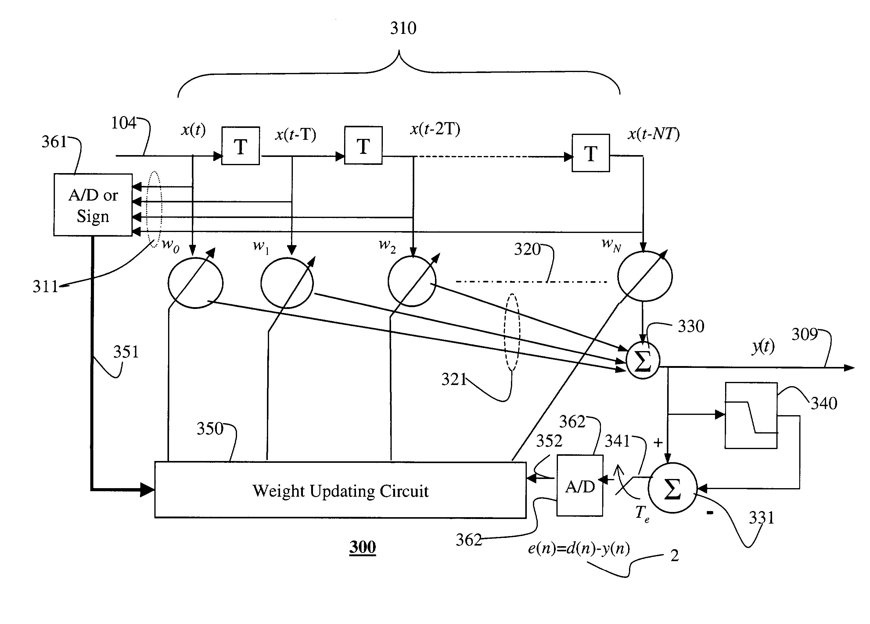
[0022]FIG. 3 shows a hybrid adaptive equalizer 300 according to the invention that includes both analog and digital components. The analog components of the equalizer 300 includes of a series of N analog tapped delay elements 310, a set of N+1 analog multipliers 320, two analog adders 330–331, and an analog decision device 340, e.g. a comparator. These analog components implement an analog tapped delay line filter.

[0023]The digital components include a weight updating circuit 350 used to adjust the weights w of the set of tap. The weights can be adjusted according to the least mean-square (LMS) error, a signed LMS error, or a recursive least-squares error, see Proakis, Digital Communications, Fourth Edition, McGraw-Hill, New York, 2001 for other variations. Inputs to the weight updating circuit 350 pass through analog-to-digital (A / D) converters 361–362.

System Operation

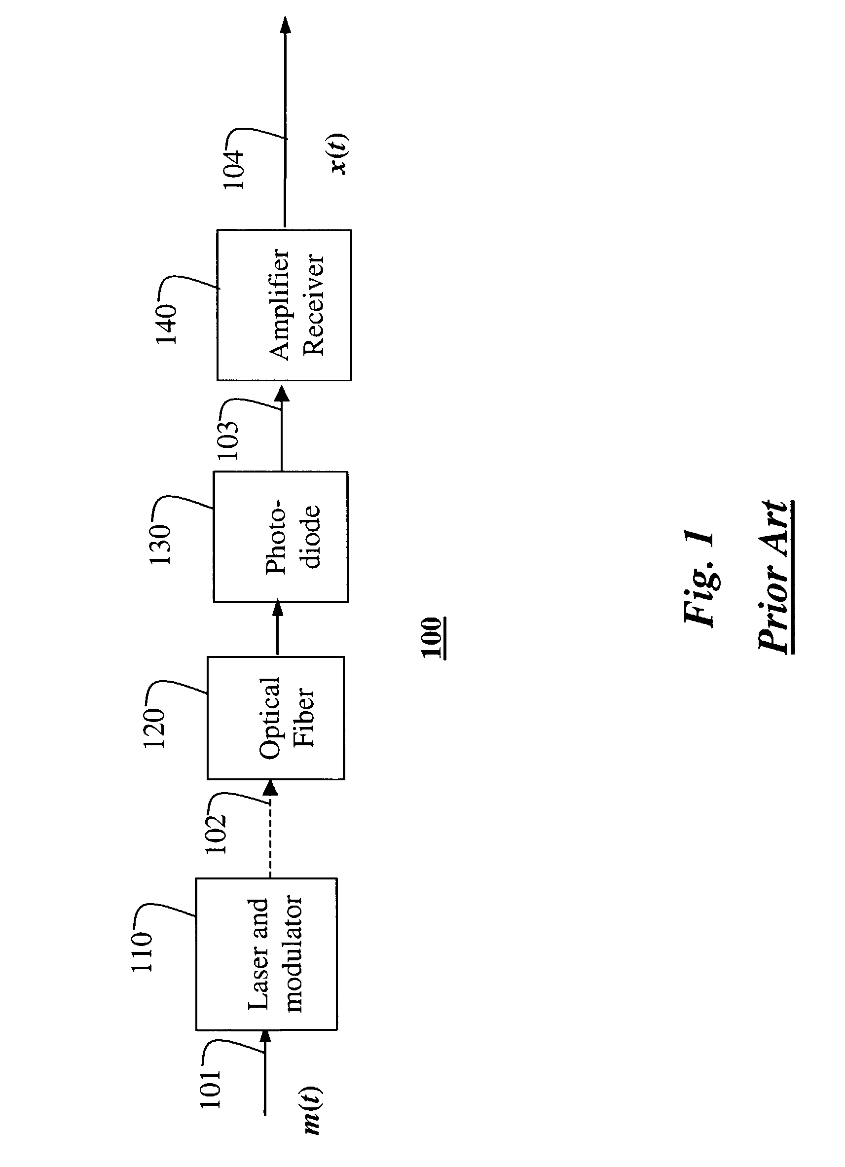
[0024]The input to the hybrid adaptive equalizer is the received signal x(t) 104 shown in FIG. 1, s...


PUM


Abstract

A method equalizes a received signal in an optical communications system. The received signal is passed through an analog delay line where it is tapped to generate a set of delayed copies of the received signal. In a set of analog multipliers, each delayed copy of the received signal is multiplied by a corresponding weight to generate a set of weighted signals that are then summed to produce an output signal. The output signal is thresholded and subtracted from the output signal to produce an error signal, which is periodically sampled. In a digital weight updating circuit, the weights are produced from digitized versions of the sampled error signal and samples of the delayed copies of the received signal.

Description

FIELD OF THE INVENTION[0001]This invention relates generally to the field of optical communications systems, and more particularly to equalizing signals received via an optical channel.BACKGROUND OF THE INVENTION[0002]FIG. 1 shows an optical communication system 100 that can use the invention. The system 100 includes laser and modulator 110 for converting a bit stream m(t) 101 at a predetermined bit rate to analog pulses of light 102. An optical fiber 120 carries the light pulses to a photo-diode 130 that converts the light pulses back to a signal 103. An amplifier / receiver 140 amplifies and filters the signal 103 to remove wideband noise and to produce a received signal x(t) 104. The bit stream is sampled at the bit rate. The samples are compared with a sampling threshold. If a sample of x(t) is greater than the threshold, then it is a one, otherwise it is a zero. This recovers the input bitstream 101.[0003]In practical systems, the received signal 104 is distorted in time and shap...

Claims


Application Information

Patent Timeline
Patent Type & Authority Patents(United States)
IPC IPC(8): H03H7/30H03H7/00H04B10/2507H04B3/06H04B10/2513H04B10/524H04B10/556H04B10/58
CPCH04B10/6971
Inventor ORLIK, PHILIPZHANG, JINYUN
Owner MITSUBISHI ELECTRIC RES LAB INC
Why Eureka
Try Eureka